TruckElectric
Well-known member
- First Name
- Bryan
- Joined
- Jun 16, 2020
- Threads
- 772
- Messages
- 2,488
- Reaction score
- 3,280
- Location
- Texas
- Vehicles
- Dodge Ram diesel
- Occupation
- Retired
- Thread starter
- #1
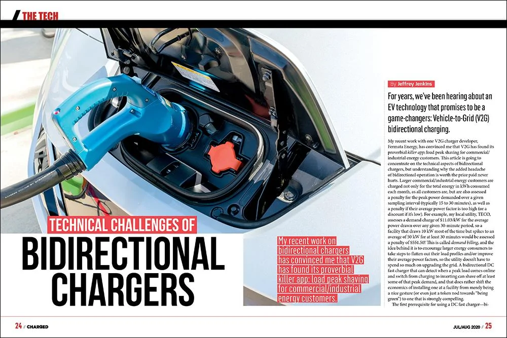
For years, we’ve been hearing about an EV technology that promises to be a game-changers: Vehicle-to-Grid (V2G) bidirectional charging. My recent work with one V2G charger developer, Fermata Energy, has convinced me that V2G has found its proverbial killer app: load peak shaving for commercial/industrial energy customers.
This article is going to concentrate on the technical aspects of bidirectional chargers, but understanding why the added headache of bidirectional operation is worth the price paid never hurts. Larger commercial/industrial energy customers are charged not only for the total energy in kWh consumed each month, as all customers are, but are also assessed a penalty for the peak power demanded over a given sampling interval (typically 15 to 30 minutes), as well as a penalty if their average power factor is too high (or a discount if it’s low).
For example, my local utility, TECO, assesses a demand charge of $11.03/kW for the average power drawn over any given 30-minute period, so a facility that draws 10 kW most of the time but spikes to an average of 50 kW for at least 30 minutes would be assessed a penalty of $551.50! This is called demand billing, and the idea behind it is to encourage larger energy consumers to take steps to flatten out their load profiles and/or improve their average power factors, so the utility doesn’t have to spend so much on upgrading the grid.
A bidirectional DC fast charger that can detect when a peak load comes online and switch from charging to inverting can shave off at least some of that peak demand, and that does rather shift the economics of installing one at a facility from merely being a nice gesture (or even just a token nod towards “being green”) to one that is strongly compelling.
The first prerequisite for using a DC fast charger—bidirectional or not—is that it and the EV have compatible DC charging ports, which is more of a problem than it really should be, as these ports are not standardized across OEMs, and are often only offered as an expensive upgrade.
For example, Nissan uses CHAdeMO, most other OEMs use CCS-1 in the US or CCS-2 in the EU, and Tesla might use any of the above or its own proprietary port design depending on the model year, country of sale and particular whim of the customer. It’s pretty much the epitome of the old engineering cliché: “standards are great because there are so many to choose from!”
Two other critical requirements for bidirectional chargers are that they must be galvanically isolated from the AC mains, and they must immediately cease operating as an inverter upon loss of power (in other words, they can’t be used as a standby generator or UPS). That last is also known (somewhat more infamously) as the “anti-islanding” provision, whose questionable rationale is to protect utility workers from being electrocuted from a power source at the load end backfeeding onto the mains (despite the fact that utility workers are trained to treat all wires as hot until bonded to earth ground, and to wear gloves when handling them).
Another common regulatory requirement is that the charger operate at very close to unity power factor (that is, it must employ Power Factor Correction, or PFC), but this functionality more or less comes for free in any charger that is bidirectional. In fact, not only can a bidirectional charger source back to the grid at near unity power factor, it can also correct bad power factor to some extent, at least for the loads downstream, and some utilities will even pay you for doing so.
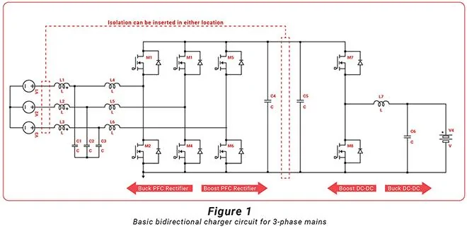
There are a myriad of different circuit arrangements that could be used to make an isolated bidirectional charger which meet the above criteria, but for the sake of brevity I’m going to concentrate on just two approaches: a 3-phase active rectifier/inverter front end (i.e. the mains-side converter) coupled to a bidirectional buck/boost converter back end (i.e. the EV-side converter), and with isolation either provided by (1) a conventional mains-frequency transformer or by (2) inserting a high-frequency DC-DC converter in between the DC link that would otherwise directly join the other two converters (e.g. between C4 and C5 in Fig. 1).
The main reason for choosing this topology is that it is pretty much the simplest one for a bidirectional EV charger that can perform power factor correction over a wide range of EV traction battery voltage relative to that of the mains. Referring to Fig. 1, the three voltage sources on the far left, V1-V3, represent the 3-phase AC mains (wired in wye, though they could be wired in delta with no functional difference), while the battery symbol on the far right, V4, represents the EV traction battery.
MOSFETs M1-M6, along with inductors L4-L6, operate as a 3-phase boost converter when in charging mode, and a buck converter in discharging mode, and as long as the DC link voltage (buffered by reservoir capacitors C4 and C5) is higher than the peak voltage of the AC mains, near unity power factor can be achieved. MOSFETs M7 and M8, along with inductor L7, comprise a bidirectional DC-DC converter that can operate as a buck when M7 is modulated and M8 is freewheeling, or as a boost when M8 is modulated and M7 is freewheeling.
Those of you paying close attention will have noted that L1-L3 have yet to be mentioned. These inductors—more commonly referred to as line reactors in this position—are inevitably required to meet surge and electromagnetic compatibility (EMC) requirements, so they are typically purchased ready-made as pre-approved components.
That just leaves the proverbial elephant in the room, which is providing galvanic isolation between the mains and the EV, and the only practical way of doing that is with a transformer. As mentioned above, this could be a mains-frequency (and likely 3-phase) type inserted in between the bidirectional charger and its connection to the mains, or a high-frequency (HF) ferrite type inserted in between the other two converters.
The biggest upsides to the mains-frequency transformer are that it will be very robust and almost certainly pre-approved as meeting worldwide safety standards, so incorporating one into the charger can make getting through safety agency testing much easier overall. Furthermore, isolation on the mains side also allows a much simpler circuit to be used for the bidirectional charger (basically the one shown in Fig. 1).
The biggest downside is that the size and weight of a transformer go up as operating frequency goes down. For example, a commercially available mains isolation transformer rated for 15 kVA (or 15 kW at unity power factor) will weigh about 90 kg (200 lb), and come in a cabinet approximately 0.5 m (20 in) on a side, while a 12.5 kW/200 kHz ferrite transformer I recently designed fits in the palm of the hand and weighs about 1 kg (2.2 lb).
There is an equally dramatic difference in price between both transformers, too—the mains version costs $1,100, while the ferrite one can be built in modest quantities (~100 units) for less than $100.
However, the mains transformer will provide bidirectional isolation right out of the box, and can be easily wired in between an existing non-isolated charger with little or no effect on the latter’s operation. In contrast, the ferrite transformer will need a whole bunch of switches and the support circuitry to drive them to operate at HF, and all of this has to be inserted into the DC link between the AC-DC active rectifier/inverter on the mains side and the DC-DC buck/boost converter on the EV side.
Hence, it has to be designed into the charger from the get-go, and since every HF ferrite transformer is bespoke, all of the burden of meeting safety agency requirements will then fall upon the charger OEM (or the magnetics design firm subcontracted for the job). All of this narrows the price differential between the two approaches, or outright inverts it, and that’s not even factoring in the much higher development effort and regulatory burden when going the HF ferrite transformer route.
Things get really interesting in bidirectional charger design when you consider all the support circuitry needed to use a HF ferrite transformer for isolation, as the circuits that do the active rectification/inversion (on the AC side) and buck/boost DC-DC conversion (on the EV side) are relatively straightforward.
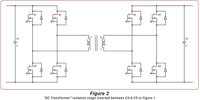
The simplest approach is to use identical full bridges on each side of the transformer, which are driven synchronously with a duty cycle just under 50% so that little filtering is required (see Fig. 2). This allows energy to flow in either direction at any time, effectively making it a transformer that operates on DC.
In fact, an electromechanical version of this circuit—with relays replacing the semiconductor switches used today—was employed to supply HV to the vacuum tubes in early car radios.
This topology is formally known as the synchronous bidirectional full-bridge, but it is more commonly referred to as a DC transformer, because that is effectively what it is. Applying PWM to this topology is notoriously difficult (because the input and output can flip sides at any time), but operating at a fixed duty means there is no way to limit overcurrent except by totally shutting down all of the switches simultaneously. Also, the leakage inductance of the transformer and the output capacitances of the switches can exact a hefty penalty on efficiency and reliability, limiting the allowable switching frequency as power goes up (right when you need it most).
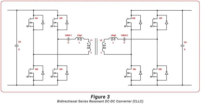
There are numerous circuit variations that address some or even all of the aforementioned downsides—adding either passive or “lossless” snubbers is the most obvious—but a particularly compelling option is to make use of the transformer leakage inductance as part of a series resonant network by inserting a calculated amount of capacitance (and, optionally, additional inductance) in series with each side of the transformer, then driving the bridge switches with a fixed duty cycle at the resultant resonant frequency (see Fig. 3).
This changes the shape of the current waveform from squarish to sinusoidal, which dramatically reduces switching losses, and it also absorbs any other stray inductances (besides transformer leakage) into the series resonant networks, eliminating the need for snubbers and allowing much higher-frequency operation.
There are two downsides to series resonant operation: output can only be regulated by varying the frequency so it still can’t limit overcurrent when operated at a fixed duty cycle; and the stability of the resonant frequency depends on the value of components (and strays) not drifting too much with time and temperature. Both of these issues have prevented wider adoption of this topology, but DC fast chargers are expensive and relatively low-volume products, so having to tweak the frequency on a per-unit basis isn’t quite so painful as it would be for, say, a Level 1 charger.
SOURCE: CHARGED
Sponsored