JayWebbMD
Well-known member
- First Name
- Jay
- Joined
- May 1, 2024
- Threads
- 5
- Messages
- 46
- Reaction score
- 92
- Location
- Pensacola, FL
- Vehicles
- 2011 Audi TTS, 2023 Genesis GV70, awaiting Beast
- Thread starter
- #1
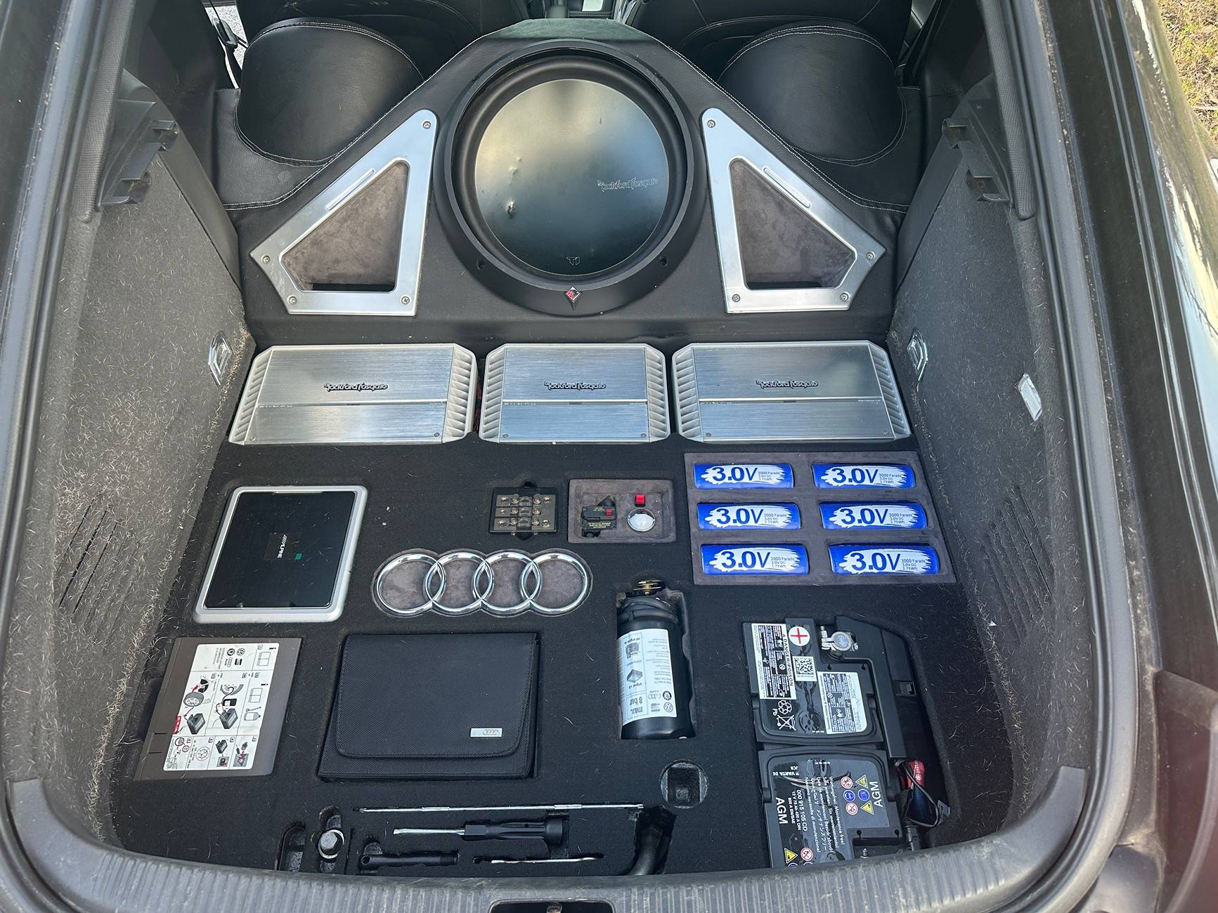
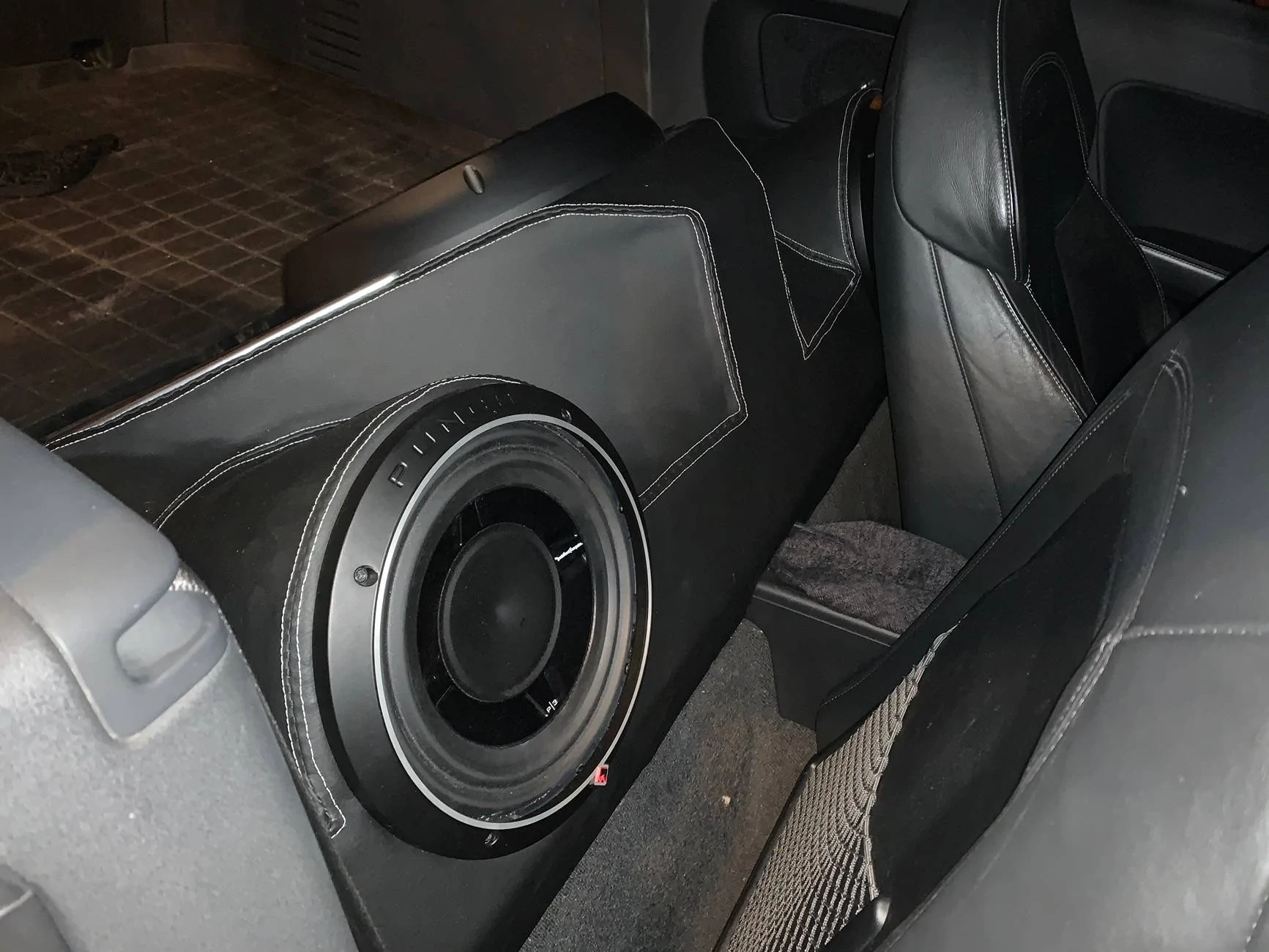
Finally finished a project that's been in the works for awhile. Its 2 shallow mount 12's in a ported box and a DIY amplifier that you can read more about below. It runs off of the 120V plug in the center console. I removed the factory subs and ran the factory sub wires into an Epicenter Micro module which is powered from a dedicated 15V output from the amplifier. It sounds fantastic. I can turn them on and off and control the level with the factory subwoofer control on the touchscreen. The factory system was good "for a factory system," but now that I've got real bass, I can lower the bass level on the radio, which lets me go to full volume without causing the door speakers to distort and I can now hear the full audio range and understand the vocals with the windows down at 70 mph, which is my bar for a good system. I know there are other easier ways to do this, but for those who like details, here's the full rundown:
Equipment:
Discussion:


Equipment:
- (2) Rockford Fosgate P3S12D2 shallow mount 12" subwoofers
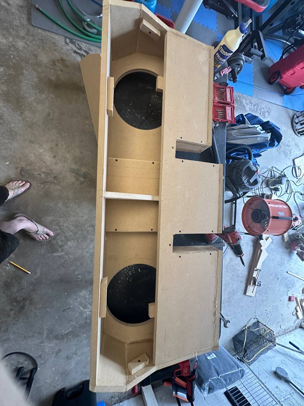
- Custom 2.5 ft^3 ported box under rear seats
- 3/4" MDF, wood glue, screws, silicon from hardware store
- Cheap black foam backed suede (https://a.co/d/gErx5zl)
- Cheap terminal cups (https://a.co/d/g1TeO1Y)
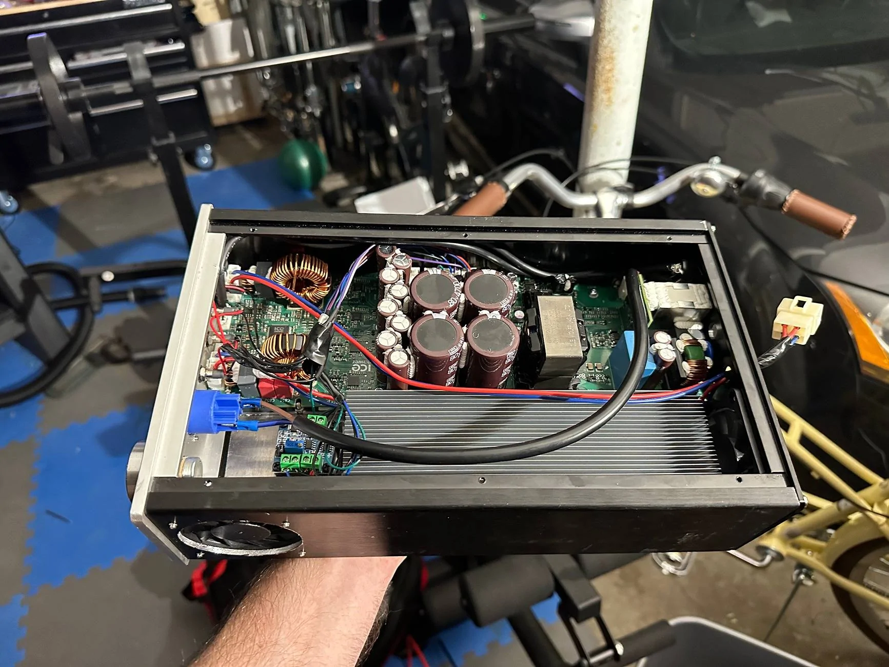
- Home Built Amplifier
- ICEPower 1200AS2 Amplifier Board, somewhere around 700 watts x 2 RMS, with built in 120/240 power supply (https://www.parts-express.com/ICEpo...ZTqyIWO7WMK7239I6Iz8TjbmFoMLj4TYL7IALlczQB01l)
- Aluminum amplifier case, 190*310*80 mm (https://www.aliexpress.us/item/3256...st_main.5.56c41802J0j5fq&gatewayAdapt=glo2usa)
- 1200AS2 Cable Kit (https://shop.icepoweraudio.com/product/1200as2-cablekit/)
- 120V 20A Power Connector (https://a.co/d/9ijXDih)
- Heatsink (https://a.co/d/jktCys1)
- (2) 5V Fans (https://a.co/d/ekLaDpJ)
- PWM Fan Controller, analog voltage to PWM (https://a.co/d/1Ksj6PA)
- Some LED's (https://a.co/d/5VrEM69)
- Stainless M3 and M4 Screws (https://a.co/d/e9gam2A)
- Nylon standoffs (https://a.co/d/0fv0MDI)
- 8AWG power wires, 3 prong AC plug from an old Monster distribution center, some other random small wires, and some spare 1/8" aluminum plates that I had laying around
- Preamp, AudioControl Epicenter Micro (https://a.co/d/hvd6kz5)
Discussion:
- Subwoofers
- I had these laying around from years ago. I did a full Rockford Fosgate system in my last car and needed to fill in some midbass between the 8" Punch Pro midranges and the T1 15" subwoofer, so I bought these, but ended up using 10's instead. I actually always hated these subs when we sold them when I worked at Best Buy because we only sold them in a 0.5 cubic foot sealed prefab box and it sounded like ass every time. I actually built the box in such a way that I could change one inner wall and extend the port to better suit JL TW3's, because I expected these to also sound like ass. Now that it's all done, I'm pretty impressed by them, so I won't be changing unless I blow these.
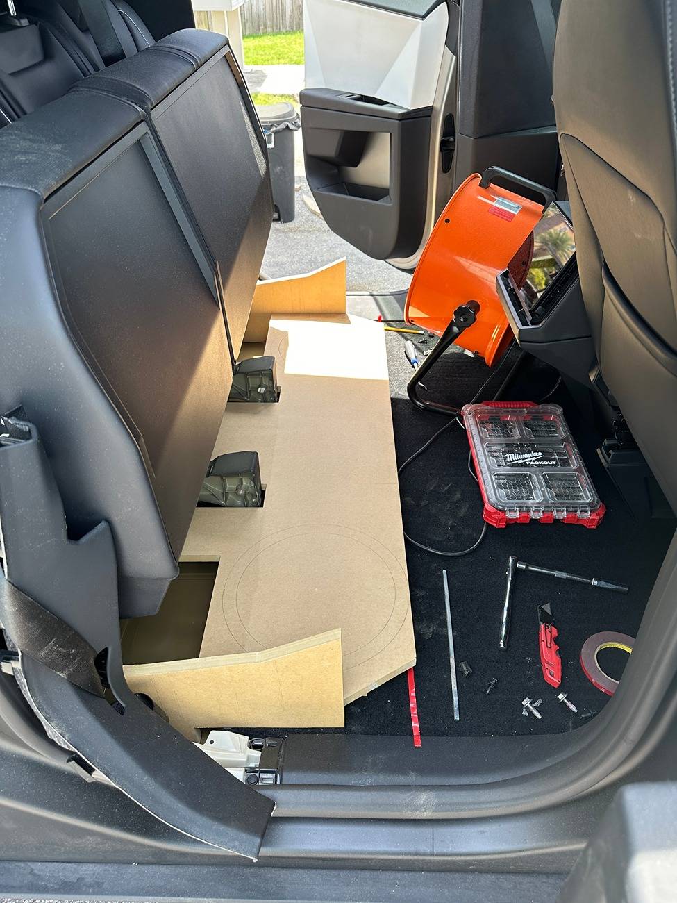
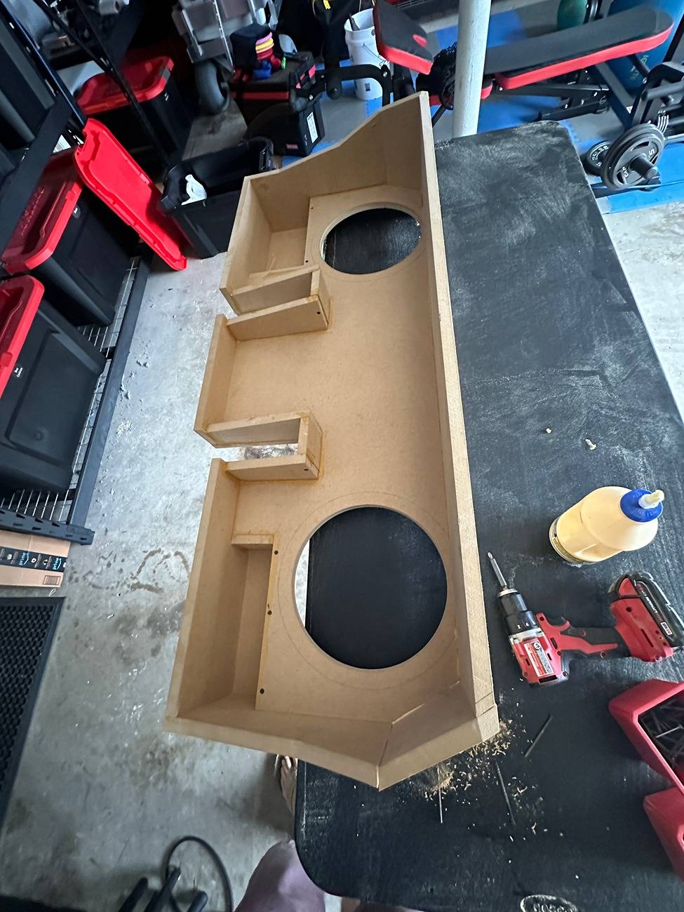
- Box
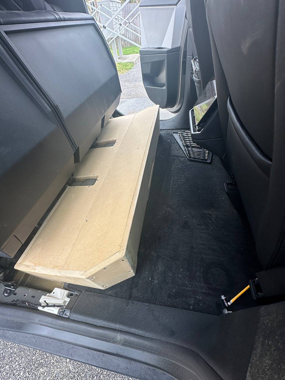
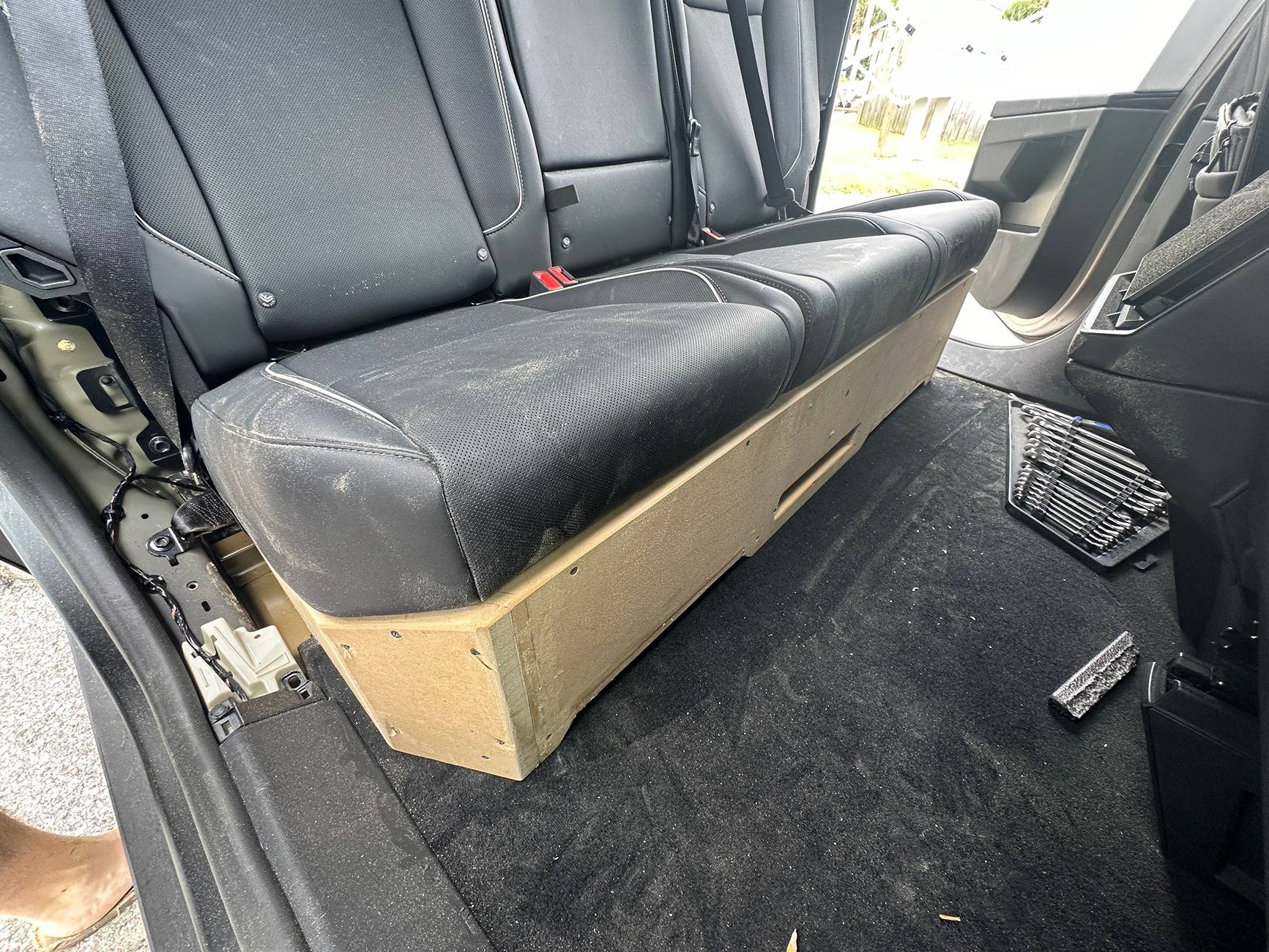
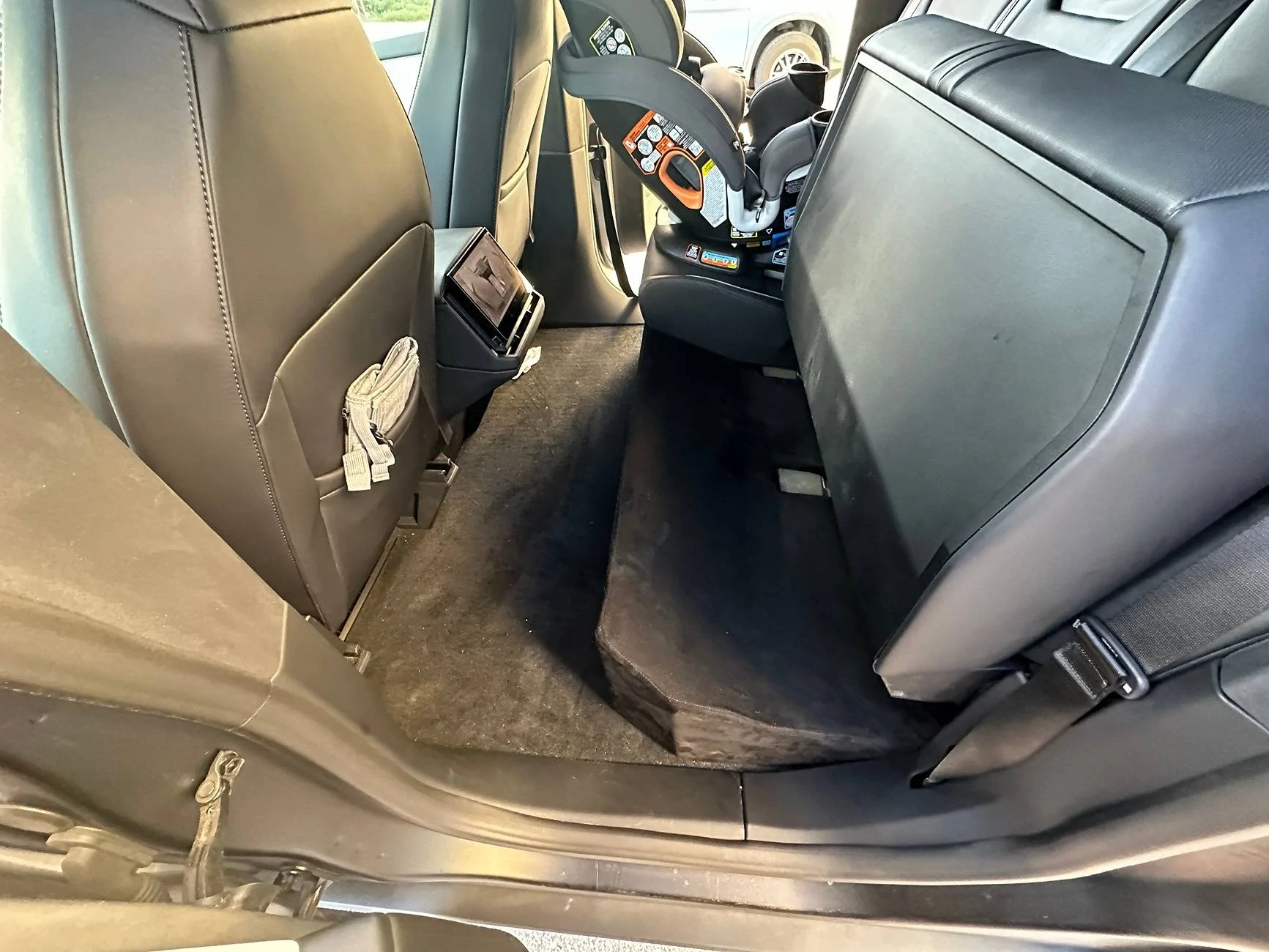
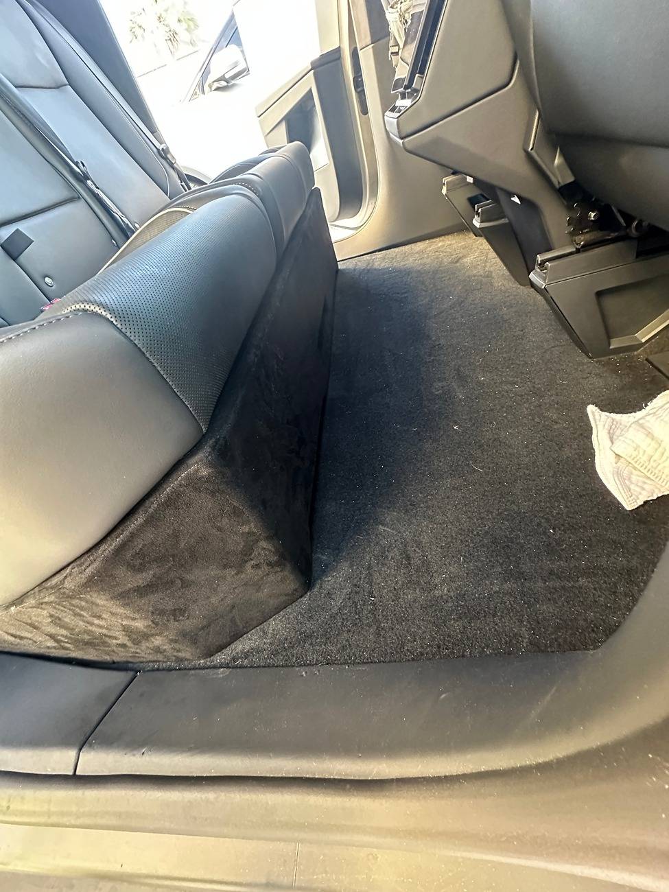
- The box was pretty complex. I needed 2.5 cubic feet not counting the port and sub volume, so I roughed out what I needed and just kind of started building the side pieces to their maximum dimensions, then came as far forward as I could, left 1" for the subs to downfire, and found I was short by about .2 cubic feet. So I ultimately had to build little extra chambers on the sides to take advantage of the extra space where it dips down to the floor. It came out extremely close to 2.5. The port area is a little less than it calls for, the front frame of the subwoofers sits on the carpet, and the seats take a strong push down to lock into place, but considering what I had to work with, it came out great and sounds awesome.
- I'm not great at upholstery, so I bought this cheap suede expecting that I would screw it up, learn from my mistakes, then redo it with real Alcantara. It came out good enough for me, so this is how it will stay.
- Amplifier
- The only other subwoofer system I've seen was the one by Tint World in Orlando where they used 48 to 12 V step down converters. Initially I wanted to beef up the 48V system with extra batteries and use 48V amplifiers. Unfortunately, the biggest 48V amplifier I could find was 300 watts RMS. I suspect this has something to do with convenience and cost. Its most likely a Class D circuit powered directly by the 48VDC input with no power conversion stage. So this is where I first got my idea to build my own amplifier.
- I found this originally: https://store.sure-electronics.com/product/619 . This board runs off of 25-50VDC and had the power and load rating I needed, so I ordered it. When it came in, I connected it to (4) 12V LiFePo4 batteries in series, which came to 52.4V. I assumed there was some leeway in the supply voltage rating. That was not the case. It jammed on my 15" in my old car for about 30 seconds, then I tried to test the limits and burned it up. Contacted the company and they said I was running it out of spec, so they wouldn't replace it. At this point I investigated the voltage in the truck a bit more. Tesla's documentation says the 48V circuit can technically range from 28 to 58 volts and the stock "48V" battery is actually 41.6 Volts and the actual voltage on my 48V accessory line was 46.8 Volts. With that kind of variability, I didn't think I could reliably count on it to charge any configuration of lithium batteries. I'm sure the 12V step down converters also charge a bit unpredictably unless there's some kind of output voltage regulation built into them.
- The other option was to run off of the 120V system. I looked at a bunch of home and DJ amps and couldn't make heads or tails of it. At least with car audio, you get RMS and Peak power ratings and you can guess how true that is based on the brand's reputation and the cost. With home and DJ amps, it was anywhere from $0.25 to $5.00 per watt and specs and reviews were all over the place. The other thing I noticed when looking at pictures of these amps with the cases off is that they have all kinds of big wire harnesses dangling all over the place that would probably not do well in a constant vibration environment. Many also had loud fans, digital displays, and other stuff that I didn't want. So I decided to build my own amp.
- Amplifier module:
- I found the ICEPower 1200AS2, which is discussed on several threads in diy audio forums. The specs are much more technical than what you'll find for any consumer ready amplifier. But suffice it to say that it should be able to reliably give me 400 watts RMS x 2 with appropriate cooling, and it seems to be doing so. You have to buy the harnesses for it separately and they didn't have all of them on parts express, so I ordered them from the manufacturer.
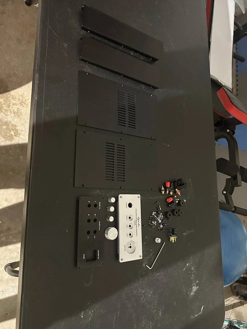
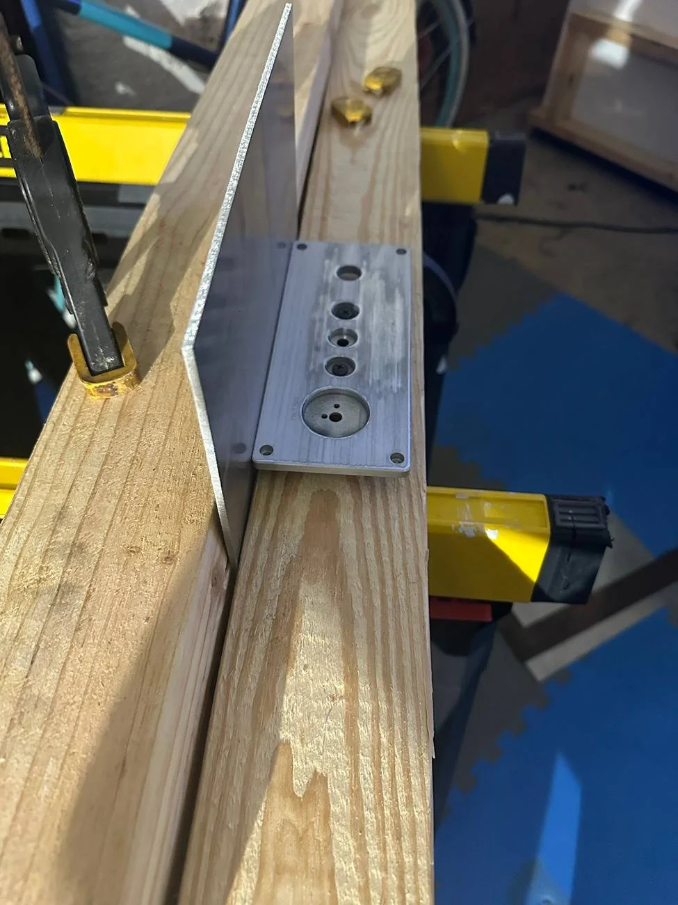
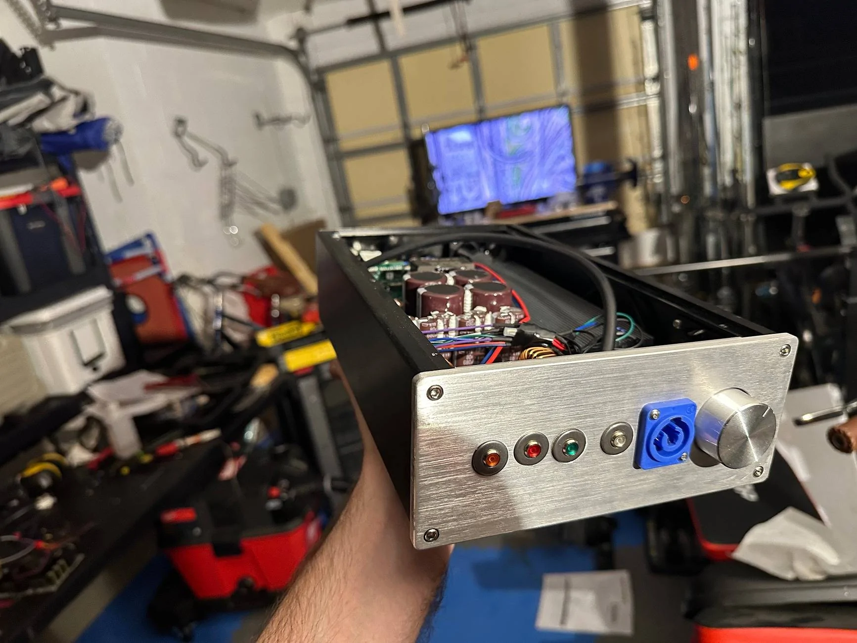
- Case:
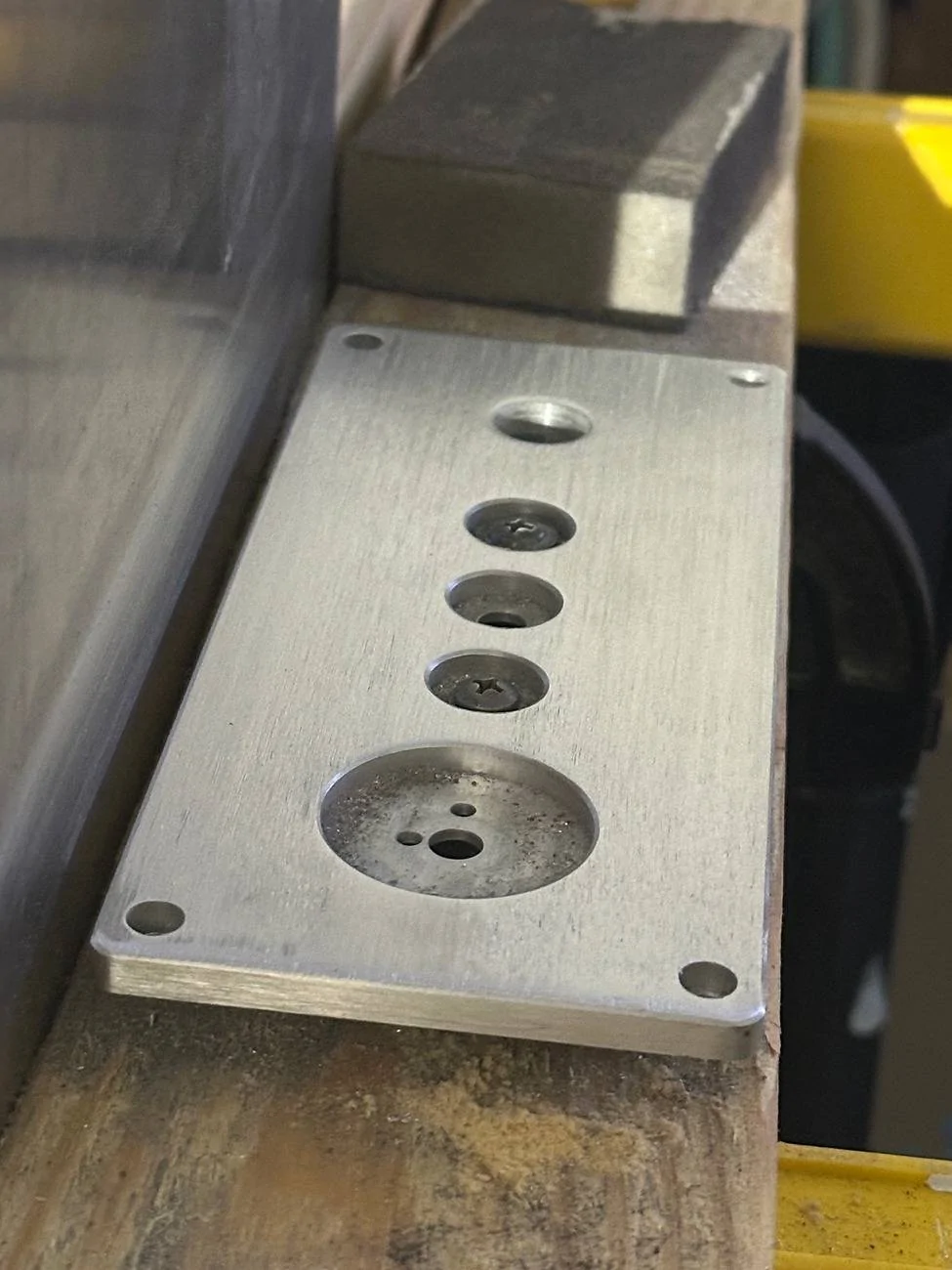
- This took forever to find a case small enough to fit between the rear seat mounts but big enough to fit the amplifier board and all of the stuff that goes with it. After hours of searching, I found the one listed above on AliExpress. It comes with all those holes and markings on it, so I had to grind all that off with a belt sander. Once it was assembled, it fit in that space with less than a few mm to spare in any direction. The board also fit exactly flush with the inner walls of the case.
- I put LED's in the holes for the tuning knobs. Those are some stainless washers I had sitting around that happened to be the right inner and outer diameter. And I had to drill one extra hole and was very lazy about it, so its off center...the only part my friend commented on in this whole project...
- The volume knob is purely decorative. I would have to build a voltage divider circuit to be able to use it as gain control and I would need two of them since its a 2 channel amp, so I just ditched that part.
- The case came with RCA jacks, speaker wire posts, and a standard 3 prong AC input. Those 3 prong AC inputs are only rated for 10 or 15 amps, but I figured I could see burst power as high as 1600 watts at around 75% efficiency, so I may be pulling over 15 amps on occasion. I initially installed the RCA jacks and speaker wire posts, but they crowded everything too much, so I ditched them for wires coming straight out from the case.
- Cooling:
- I know this is a weird way to do cooling, but its 2 fans, one blowing in, one blowing out. They're controlled by a little PWM controller that takes the temperature signal from the board (0-3VDC) and converts it to a PWM signal to drive the fans. The board itself is built on top of a flat aluminum plate. I put 2 layers of 1/8" aluminum on the bottom of the case to level it and mounted the board and the heatsink to them. It should be enough aluminum mass to effectively transfer the heat from the board to the heatsink and the fans should ensure good airflow in and out of the case.
- Preamp:
- I originally installed a PAC high power line output converter and could only get the amp to pull a max of 0.7 kW from the outlet with the LOC level, sub level on the radio, and volume all maxed. The amp itself doesn't have built in gain control, so I needed something to boost it. This could be done with a cheaper module than the Epicenter since the factory subwoofer signal is already a low pass signal, but I wanted a little more tunability. I considered a few others, but the 15V output from the amplifier is limited at 500 mA and others required a little more than that. The Epicenter only needed 300 mA.
- I have the Epicenter on the lowest voltage output setting, have both tuning knobs all the way down, and factory subwoofer level at -4.0 for standard listening and occasionally turn it up to 0.0. So it clearly has a lot more to give if needed.
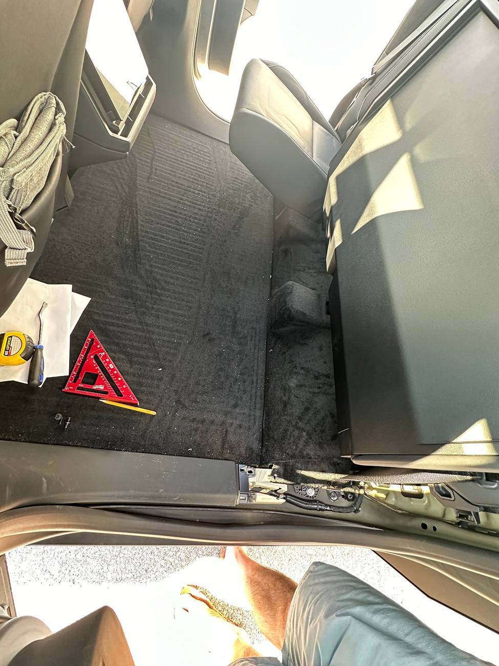
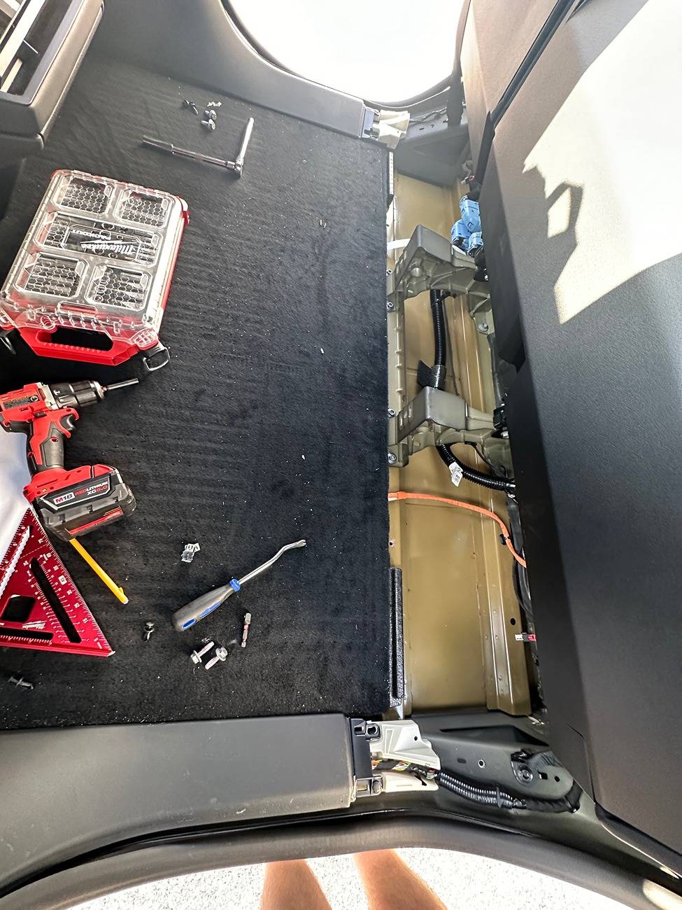
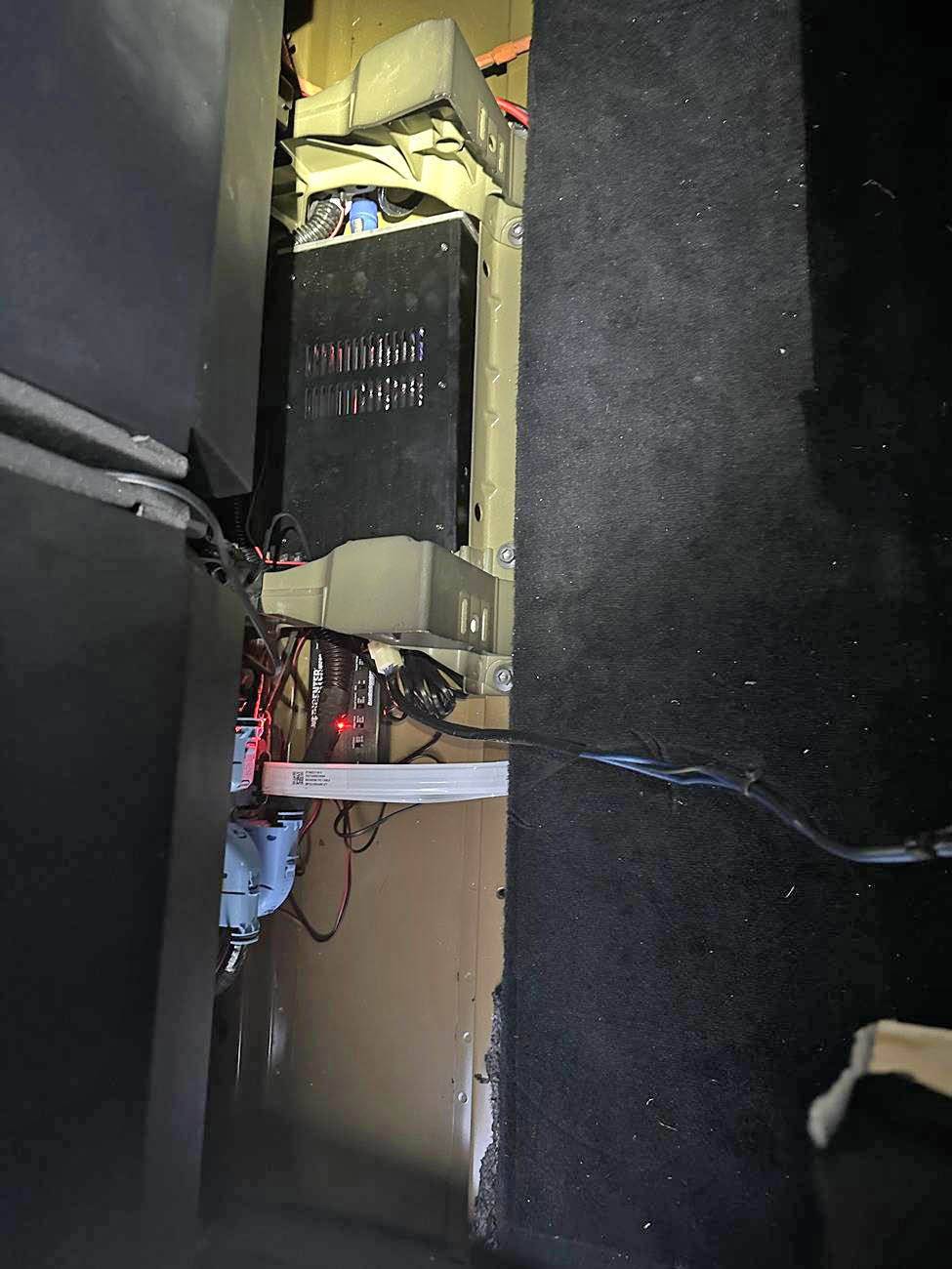
- Wiring:
- The power wires are 8 gauge wires lazily run beneath the carpet to the center console. You can't tell when its all put back together unless you look from the side and see the carpet is just a little bit lifted up in the center. You could probably take the time to cut holes in the styrofoam that's attached to the bottom of the carpet to make channels for the wires, but I didn't care that much. You would probably not want to run the wires all the way to the side because you'd be running non-shielded 120V cables a long way right next to sensitive data wires.
- I wanted to tap into the wires before the outlet, but it turns out that the orange tape wrapped wires are individually shielded wires, so to tap into them, I'd have to destroy the shielding or massively dissect into them, which I feel like would be a safety hazard and maybe invalidate warranties and/or insurance. These shielded wires continue all the way to the outlet itself, which is sealed and can't be disassembled. So to simplify everything, I just hid the wire all the way until its in the console, then have it plugged into the outlet. The other nice thing about that is I can unplug it if I need to.
Sponsored
") .
.