TruckElectric
Well-known member
- First Name
- Bryan
- Joined
- Jun 16, 2020
- Threads
- 772
- Messages
- 2,488
- Reaction score
- 3,280
- Location
- Texas
- Vehicles
- Dodge Ram diesel
- Occupation
- Retired
- Thread starter
- #1
Tesla Semi 4680 Battery Pack Engineering Analysis

By: George Bower
We estimate the pack physical layout, its electrical voltage, series /parallel configuration, and cooling configuration
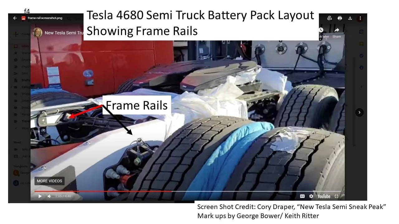
Our Engineering Consultant Keith Ritter has looked at a video taken of the Tesla Semi by Cory Draper titled “New Tesla Semi Sneak Peak”. From this video, he has estimated the physical battery pack layout, the electrical configuration, and the cooling configuration. Please note that this is just an educated estimate based on the evidence we have to date. Tesla has kept the details of the pack a secret, so we take a stab at piecing together the puzzle.
Summary
The physical layout is shown in the following two figures: a top view and an end view of what we think the pack might look like. We think the pack will go all the way from behind the front wheels to the back wheels. That puts the length of the pack at around 105 inches. The pack would be under the cab but also extend behind the cab. It would fill in between the frame rails and consist of a center section and 2 outboard sub-packs on the outside of the frame rails. The depth of the pack is estimated to go from the bottom of the cab to approximately 9 inches above the pavement.
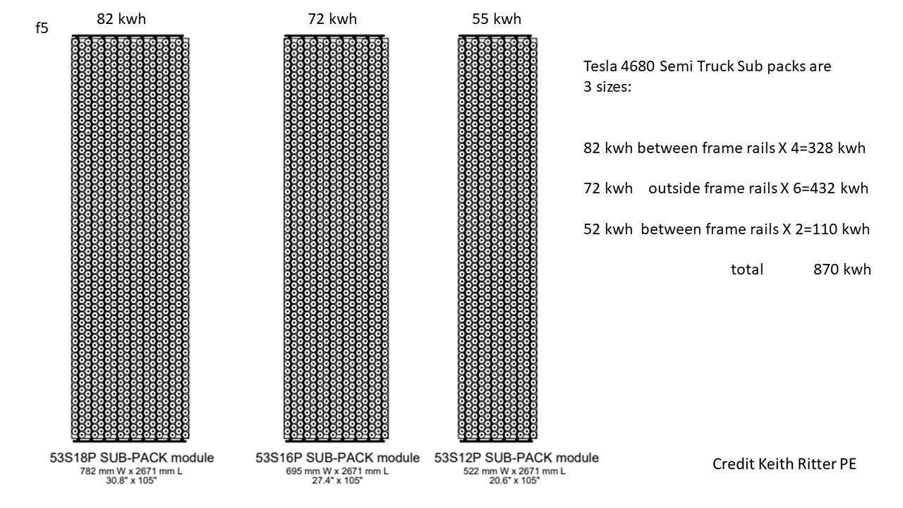
The pack center section would consist of six layers of sub-packs laid out horizontally. The two outboard packs might be on their sides vertically with three packs on each side. The outside of the pack would be protected by the outboard frame rails. It would span the entire 8’ width of the Semi truck. The usable width of the pack would be around 72 inches.
We estimate that the 500-mile pack will be approximately 875 kWh and 900 Volts DC. Total pack weight (not just cells) of 9243 pounds taking credit for reduced weight of current collectors from the higher voltage. The new Model S Plaid pack is 450 volts, so the Semi pack would basically be two times the Voltage. In addition, Proterra is running around 900 V in their bus packs. This should keep current levels in the headers to a manageable level and save weight on conductors.
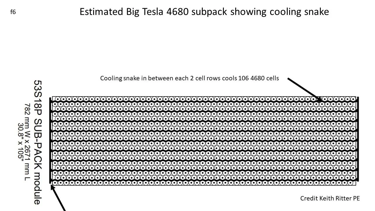
Based on a Sandy Munro presentation, we now think that Tesla will maintain its snake cooling ribbon configuration that it has had since day one, only updated to be similar to the Model 3, where the cells are glued to the cooling snake. The cooling snakes would run length-wise in between every two rows of cells. Each cooling snake would cool a maximum of 106 4680 cells.
Detailed Description
The following is from our engineering consultant Keith Ritter:
“Like most, prior to completing a deep-dive into semi-truck structural design principles, George and I had originally assumed the Tesla semi-pack would be a stacked series of monolithic structural slabs spanning between the front and rear wheels and almost to the edges on either side. They would stack 4-5 layers high and act as the core vehicle structure between the front and rear wheels.
This is how Tesla proposes to do it on their future unibody-based light vehicles. But heavy commercial vehicles have very different structural requirements. The weight-bearing loads are huge. A loaded trailer imposes about 10 tons of point load on the semi-tractor’s 5th wheel. In addition, the Semi itself weighs almost 10 tons.
To distribute that 20 tons to the semi’s front and rear suspension system and axles requires two massive 300 mm- deep high-strength-steel “C” beams called “frame rails” running from bumper to bumper to act as a “spine”. Truck manufacturers have globally standardized on this beam architecture, along with their spacing and dimensions. Most major suspension systems are pre-engineered to pair with them.
When we reviewed all available photos and videos of the Tesla Semi, it was clear to us that they, too, had adopted this frame-rail-based structural design standard, with tweaks to provide additional sub-structures to attach the heavy battery packs.
Reviewing available images and photos of other manufacturers’ Class 8 electric vehicles under production, it was clear to us that monolithic slab-based structural packs were not viable solutions in this market segment. Tesla must be using a sub-pack solution to fit the battery around the structure.
I was able to zoom in on the tires and get the tire size, then use the tires as a scale. They are 295/75R 22.5's, which the tire data shows are just over 40" dia. I then scaled the net usable distance between the front drivers and the steer tires, about 115". Both from the backside views + the side profile, it was evident that the usable vertical space for the pack was from the top of the frame rails to about 9" above the ground.
Also, it appeared there was another C-rail that started where the top steel deck plate was behind the cab, about 12" inboard from the outside edge of the cab. Assuming the cab is about 96" wide, that means we have a working pack width of about 72".
I assumed the rails are std spacing - 850 mm outside-to-outside - and 300 mm deep and with 90 mm top and bottom flanges. I added the outboard sub-C-rail that provides additional pack support + crash protection, along with a couple of small cross members within the C-rails to support the horizontal sub-pack modules inside the rails.
I included large frame rail cross-members at either end of the pack to handle torsional issues, though torsion is not as much as with an ICE rig, as the axially-mounted driver motors don't induce the longitudinal torque of an ICE engine/transmission on the frame.
I assumed each sub-pack was 100 mm high. Cells 4 mm apart in both directions. Side snake cooling, one snake per two columns, running in the serial direction. 53S max means 53 cells x 2 max per snake = 106 cells max per snake. I assumed all modules would have even # of cell columns to optimize snake utilization and space efficiency.
For the S-dimension (the long dimension), I added 30 mm to the cells-only dimension to allow for the glycol manifolds plus end current collectors. The P dimension (the short dimension) was cells-only, as the cells bump directly to the sub-pack case frame.
I looked at configurations running the cooling snakes laterally rather than axially, but it was a much less space-efficient way. We need every cubic mm to fit 875 kWh in the available space.
The pack model I created uses a slightly different pack peak voltage than what we had previously assumed - 900 VDC, not 800. I believe the Plaid pack is 450 VDC, so Tesla may be going to slightly higher voltages to reduce design amperage and bus bar, motor winding, and power electronic component sizes and weights. I believe Proterra, the US’ major Class 8 BEV transit-vehicle manufacturer, also typically designs around 900 VDC. “
SOURCE: INSIDEEVs
By: George Bower
We estimate the pack physical layout, its electrical voltage, series /parallel configuration, and cooling configuration
Our Engineering Consultant Keith Ritter has looked at a video taken of the Tesla Semi by Cory Draper titled “New Tesla Semi Sneak Peak”. From this video, he has estimated the physical battery pack layout, the electrical configuration, and the cooling configuration. Please note that this is just an educated estimate based on the evidence we have to date. Tesla has kept the details of the pack a secret, so we take a stab at piecing together the puzzle.
Summary
The physical layout is shown in the following two figures: a top view and an end view of what we think the pack might look like. We think the pack will go all the way from behind the front wheels to the back wheels. That puts the length of the pack at around 105 inches. The pack would be under the cab but also extend behind the cab. It would fill in between the frame rails and consist of a center section and 2 outboard sub-packs on the outside of the frame rails. The depth of the pack is estimated to go from the bottom of the cab to approximately 9 inches above the pavement.
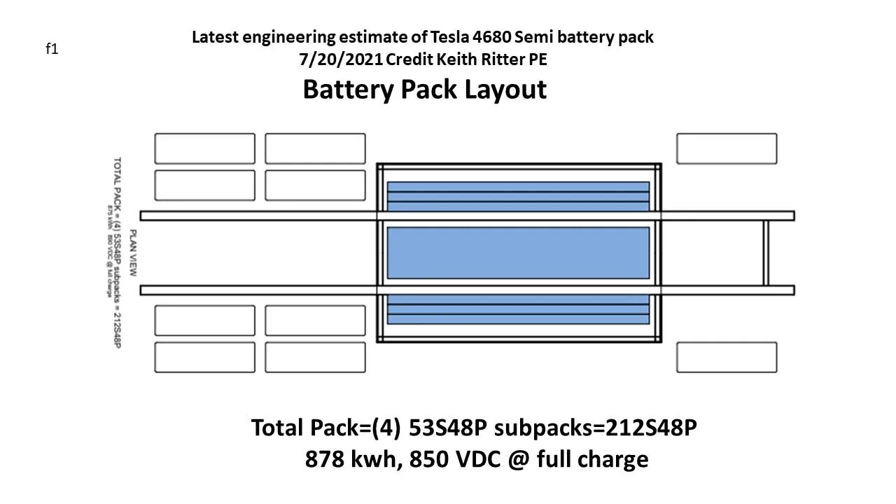
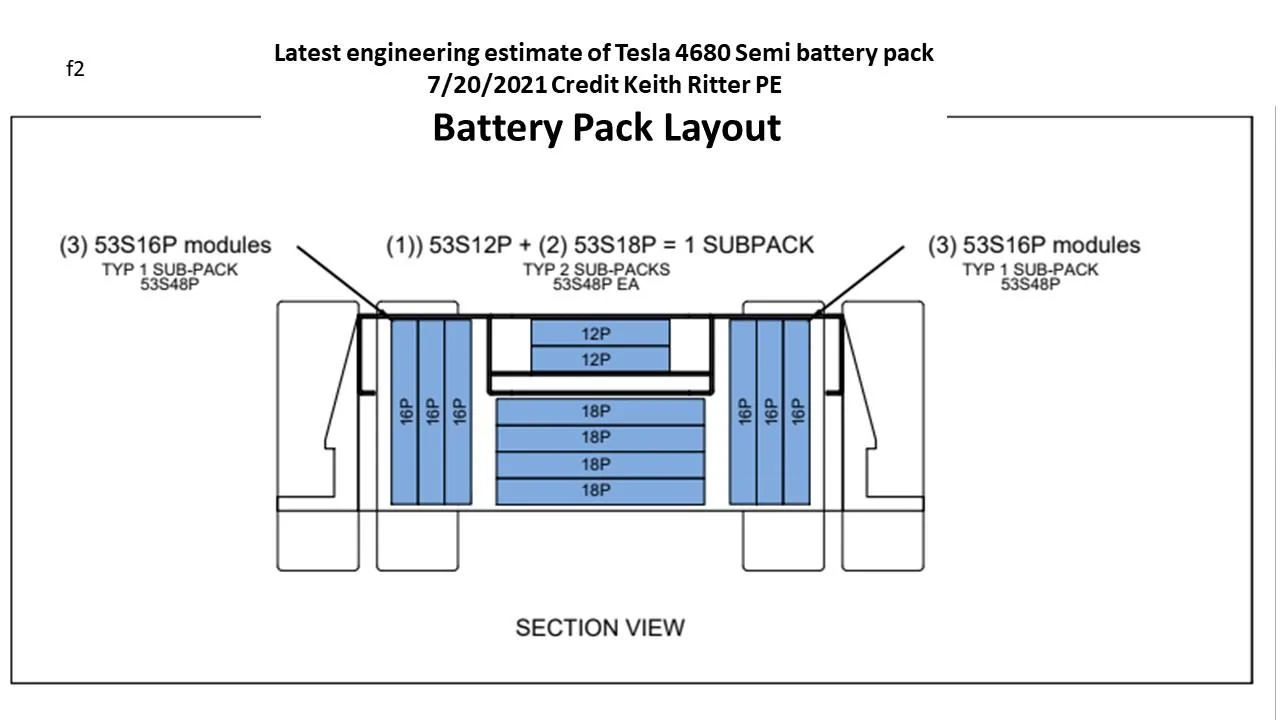
The pack center section would consist of six layers of sub-packs laid out horizontally. The two outboard packs might be on their sides vertically with three packs on each side. The outside of the pack would be protected by the outboard frame rails. It would span the entire 8’ width of the Semi truck. The usable width of the pack would be around 72 inches.
We estimate that the 500-mile pack will be approximately 875 kWh and 900 Volts DC. Total pack weight (not just cells) of 9243 pounds taking credit for reduced weight of current collectors from the higher voltage. The new Model S Plaid pack is 450 volts, so the Semi pack would basically be two times the Voltage. In addition, Proterra is running around 900 V in their bus packs. This should keep current levels in the headers to a manageable level and save weight on conductors.
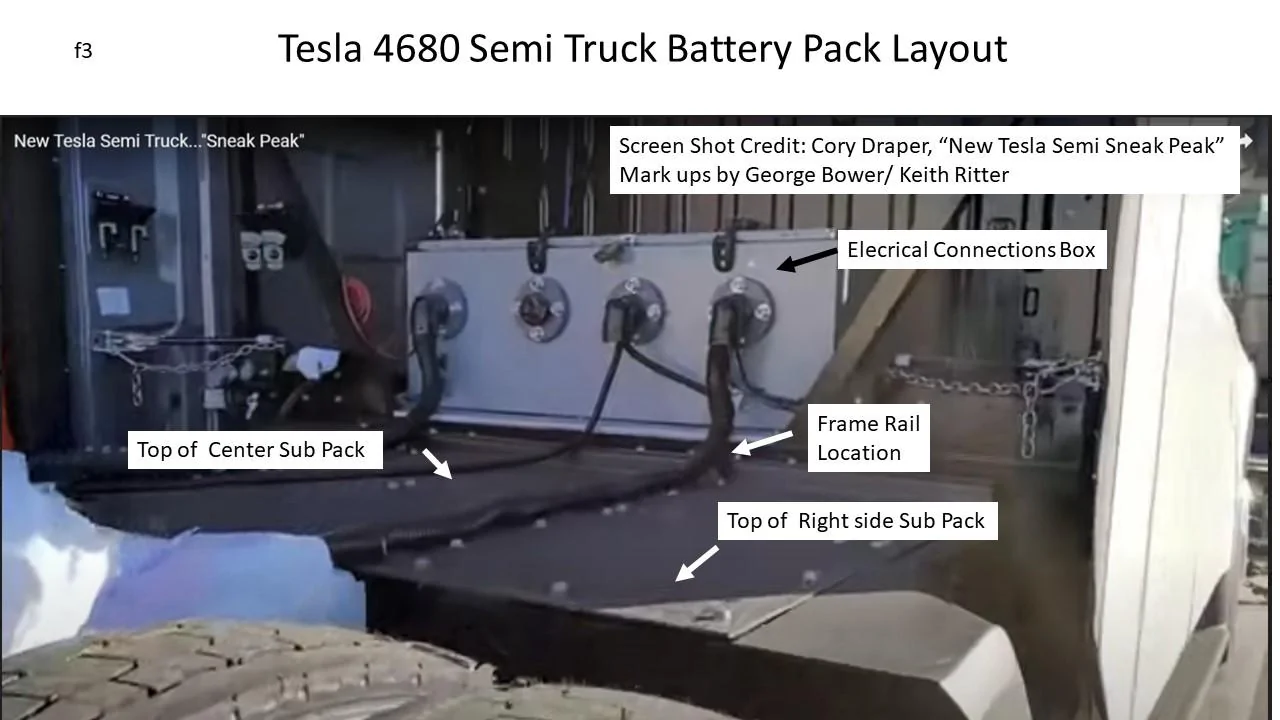
Based on a Sandy Munro presentation, we now think that Tesla will maintain its snake cooling ribbon configuration that it has had since day one, only updated to be similar to the Model 3, where the cells are glued to the cooling snake. The cooling snakes would run length-wise in between every two rows of cells. Each cooling snake would cool a maximum of 106 4680 cells.
Detailed Description
The following is from our engineering consultant Keith Ritter:
“Like most, prior to completing a deep-dive into semi-truck structural design principles, George and I had originally assumed the Tesla semi-pack would be a stacked series of monolithic structural slabs spanning between the front and rear wheels and almost to the edges on either side. They would stack 4-5 layers high and act as the core vehicle structure between the front and rear wheels.
This is how Tesla proposes to do it on their future unibody-based light vehicles. But heavy commercial vehicles have very different structural requirements. The weight-bearing loads are huge. A loaded trailer imposes about 10 tons of point load on the semi-tractor’s 5th wheel. In addition, the Semi itself weighs almost 10 tons.
To distribute that 20 tons to the semi’s front and rear suspension system and axles requires two massive 300 mm- deep high-strength-steel “C” beams called “frame rails” running from bumper to bumper to act as a “spine”. Truck manufacturers have globally standardized on this beam architecture, along with their spacing and dimensions. Most major suspension systems are pre-engineered to pair with them.
When we reviewed all available photos and videos of the Tesla Semi, it was clear to us that they, too, had adopted this frame-rail-based structural design standard, with tweaks to provide additional sub-structures to attach the heavy battery packs.
Reviewing available images and photos of other manufacturers’ Class 8 electric vehicles under production, it was clear to us that monolithic slab-based structural packs were not viable solutions in this market segment. Tesla must be using a sub-pack solution to fit the battery around the structure.
I was able to zoom in on the tires and get the tire size, then use the tires as a scale. They are 295/75R 22.5's, which the tire data shows are just over 40" dia. I then scaled the net usable distance between the front drivers and the steer tires, about 115". Both from the backside views + the side profile, it was evident that the usable vertical space for the pack was from the top of the frame rails to about 9" above the ground.
Also, it appeared there was another C-rail that started where the top steel deck plate was behind the cab, about 12" inboard from the outside edge of the cab. Assuming the cab is about 96" wide, that means we have a working pack width of about 72".
I assumed the rails are std spacing - 850 mm outside-to-outside - and 300 mm deep and with 90 mm top and bottom flanges. I added the outboard sub-C-rail that provides additional pack support + crash protection, along with a couple of small cross members within the C-rails to support the horizontal sub-pack modules inside the rails.
I included large frame rail cross-members at either end of the pack to handle torsional issues, though torsion is not as much as with an ICE rig, as the axially-mounted driver motors don't induce the longitudinal torque of an ICE engine/transmission on the frame.
I assumed each sub-pack was 100 mm high. Cells 4 mm apart in both directions. Side snake cooling, one snake per two columns, running in the serial direction. 53S max means 53 cells x 2 max per snake = 106 cells max per snake. I assumed all modules would have even # of cell columns to optimize snake utilization and space efficiency.
For the S-dimension (the long dimension), I added 30 mm to the cells-only dimension to allow for the glycol manifolds plus end current collectors. The P dimension (the short dimension) was cells-only, as the cells bump directly to the sub-pack case frame.
I looked at configurations running the cooling snakes laterally rather than axially, but it was a much less space-efficient way. We need every cubic mm to fit 875 kWh in the available space.
The pack model I created uses a slightly different pack peak voltage than what we had previously assumed - 900 VDC, not 800. I believe the Plaid pack is 450 VDC, so Tesla may be going to slightly higher voltages to reduce design amperage and bus bar, motor winding, and power electronic component sizes and weights. I believe Proterra, the US’ major Class 8 BEV transit-vehicle manufacturer, also typically designs around 900 VDC. “
SOURCE: INSIDEEVs
Sponsored