Momo
Member
- Joined
- Jun 14, 2020
- Threads
- 0
- Messages
- 9
- Reaction score
- 5
- Location
- Tx
- Vehicles
- Cybertruck (reserved) I can't bring myself to buy nothing else
- Occupation
- Clinical Pharmacist
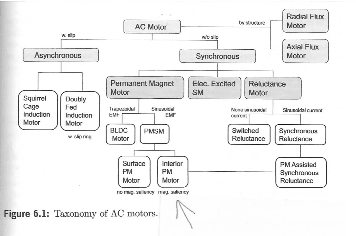
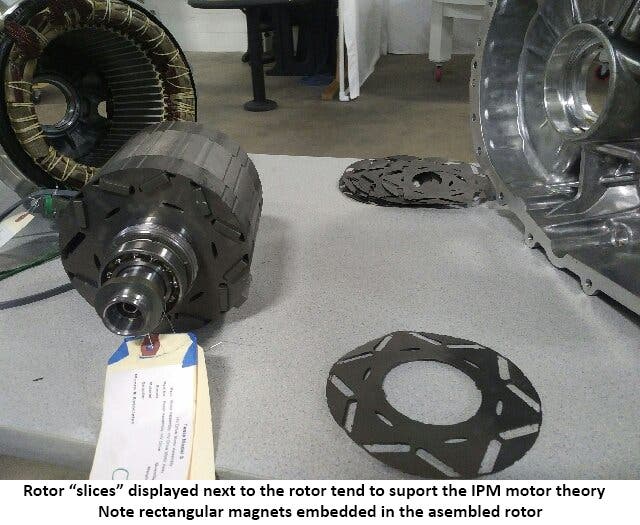
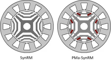
I'm not versed in motor mechanics. Can you explain the difference between the Permanent magnet motor Lucid Air will use and why the chief engineer touts it as a better motor than what Tesla has.Since Model 3 uses both an induction and reluctance it's a good guess that the dual motor CT will be similar set up. With the single motor CT being an induction? Does that mean the 3 motor uses 2 reluctance motors? Or do we think the 3 motor is plaid with some other setup?
Sponsored