Sponsored
My Swing Away Spare Tire Carrier Rack in Bumper Hitch - Off-Center, Easy Lift Feature, $99 Custom DIY
- Thread starter Bobo_LaDouche
- Start date
- Watchers 21
sielingfan
Member
- Joined
- Aug 16, 2024
- Threads
- 2
- Messages
- 17
- Reaction score
- 25
- Location
- New Mexico
- Vehicles
- Cybertruck AWD/Dual Motor
I love the idea of this but..... am I crazy, or does that hitch already look like it's getting torqued out of position?
OP
OP
Bobo_LaDouche
Well-known member
- Joined
- Nov 13, 2024
- Threads
- 8
- Messages
- 179
- Reaction score
- 268
- Location
- Carson City, Nevada
- Vehicles
- Cybertruck, Model 3
- Thread starter
- #18
Nothing is bent or deformed. There is some slop when opened, due to the way the 2" tube sits inside the hitch (as all hitches do). I mentioned that I am working on a fix. So this rocks right with the tire in place, and rocks left when opened - all due to the slop I mentioned.I love the idea of this but..... am I crazy, or does that hitch already look like it's getting torqued out of position?
OP
OP
Bobo_LaDouche
Well-known member
- Joined
- Nov 13, 2024
- Threads
- 8
- Messages
- 179
- Reaction score
- 268
- Location
- Carson City, Nevada
- Vehicles
- Cybertruck, Model 3
- Thread starter
- #19
Yes, 12" trailer extension solid-steel type. It sticks out 9.5 inches beyond the hitch, and the lower cross bar (far side) is welded 5 inches beyond the hitch; the the extender sticks out 4" beyond this, so I can put my umbrella holder in there. This sets the tire 6" from the bumper, and the upper swing arm 3" from the bumper. In this proto-type 1, I left a little room for wriggle, which is not needed. You could shave an inch here, but the camera is clear as-is.First off I wanna say you did amazing job! It’s very low profile, proficient, it’s perfect!
Questions:
Did you use a 12” trailer extension?
Basically 4-2”x2” 3/16” square tube
1.20” horizontal 2x2 square tube
2.40” horizontal 2x2 square tube
3.20” vertical 2x2 square tube
4. 9” deep 2x2 “for tire mount to slider piece” sq tube
5. 9” slider piece 2 1/2 x 2 1/2
6. 12” 10k lb trailer tongue extension? Is this 3/16 inch thick or is it a solid steel tongue extension? And is that the correct size 12 inches?
I’m going to attempt to try to build this! Not sure how well I’m going to do. Lol. Thanks for posting this!
Your parts list is correct. Also, 3/16 square plate to mount the tire to (12x12" was the purchase size, but 7.5" x 7.5 will do.) Nuts and bolts for mounting; threading tool for these, or a tack weld. Scrap for gussets (~8).
Good luck, I am here for questions, but I think as you get into this you will see it is quite simple.
The critical part is to get the swing arms the correct length. In the end, you can weld the tire face-plate last, and this allows you an inch or two lee-way.
Last edited:
mbrockus
Well-known member
- First Name
- Mark
- Joined
- Jan 31, 2024
- Threads
- 7
- Messages
- 398
- Reaction score
- 430
- Location
- Conway, WA
- Vehicles
- Model 3, Model X, AWD CT
- Occupation
- President of the Anonymous of the Anonymous Club
Way to be creative and also come up with a kick ass solution.
Cybertruck Dude
Well-known member
- First Name
- Ed
- Joined
- Nov 29, 2023
- Threads
- 1
- Messages
- 167
- Reaction score
- 159
- Location
- Illinois
- Vehicles
- Cybertruck
- Occupation
- OperatingEngineer
I actually went and got the steel square 3/16” tubing yesterday. I got 10 feet of the 2 x 2. And a foot of the 2 1/2 x 2 1/2. I forgot to get the plate. But that’s OK I don’t even have a spare tire yet!?.Yes, 12" trailer extension solid-steel type. It sticks out 9.5 inches beyond the hitch, and the lower cross bar (far side) is welded 5 inches beyond the hitch; the the extender sticks out 4" beyond this, so I can put my umbrella holder in there. This sets the tire 6" from the bumper, and the upper swing arm 3" from the bumper. In this proto-type 1, I left a little room for wriggle, which is not needed. You could shave an inch here, but the camera is clear as-is.
Your parts list is correct. Also, 3/16 square plate to mount the tire to (12x12" was the purchase size, but 7.5" x 7.5 will do.) Nuts and bolts for mounting; threading tool for these, or a tack weld. Scrap for gussets (~8).
Good luck, I am here for questions, but I think as you get into this you will see it is quite simple.
The critical part is to get the swing arms the correct length. In the end, you can weld the tire face-plate last, and this allows you an inch or two lee-way.
Did you drill the bolt 1 inch from the end. It looks a little bit longer maybe a 1 1/2”?
I really like this design!
Now you have me curious as to what you’re going to change with it ?? ? Gen 2: Your thoughts??
The only thing I am going add to it, will be a welded plate with a hole to lock your tire with a cable. Attached to the main hitch so it doesn’t get stolen. Even if they do manage to get the bolt off they still can’t take the tire. Also plastic caps ends for the 2 x 2 holes, that I found on Amazon. Your thoughts??
I didn’t see any pictures of the umbrella holder?
When this is all said and done. I’m gonna try to find a Beastly tire cover for the back of it!?
HickoryGoose
Well-known member
- First Name
- Gilles
- Joined
- Jun 18, 2020
- Threads
- 0
- Messages
- 63
- Reaction score
- 94
- Location
- Fall City, WA
- Vehicles
- 2024 FS AWD CT, 2018 M3DM
- Occupation
- Clinical Scientist
I’ll be asking my talented neighbor for a hand with a copy. Having the spare in the bed is a pain. Thanks for sharing!!
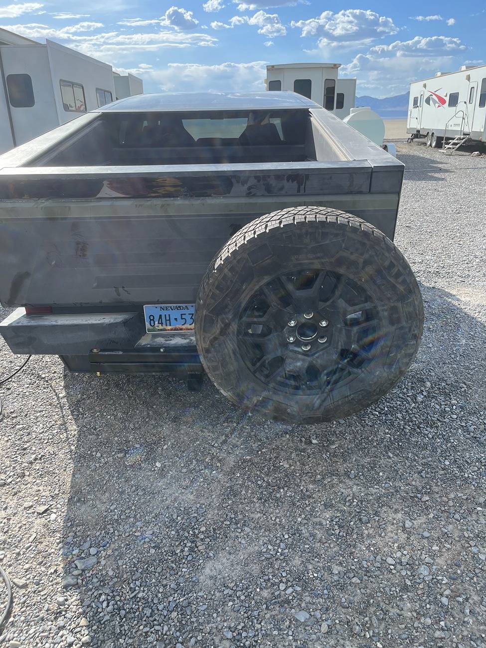
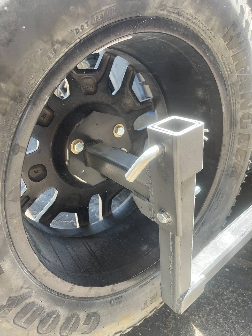
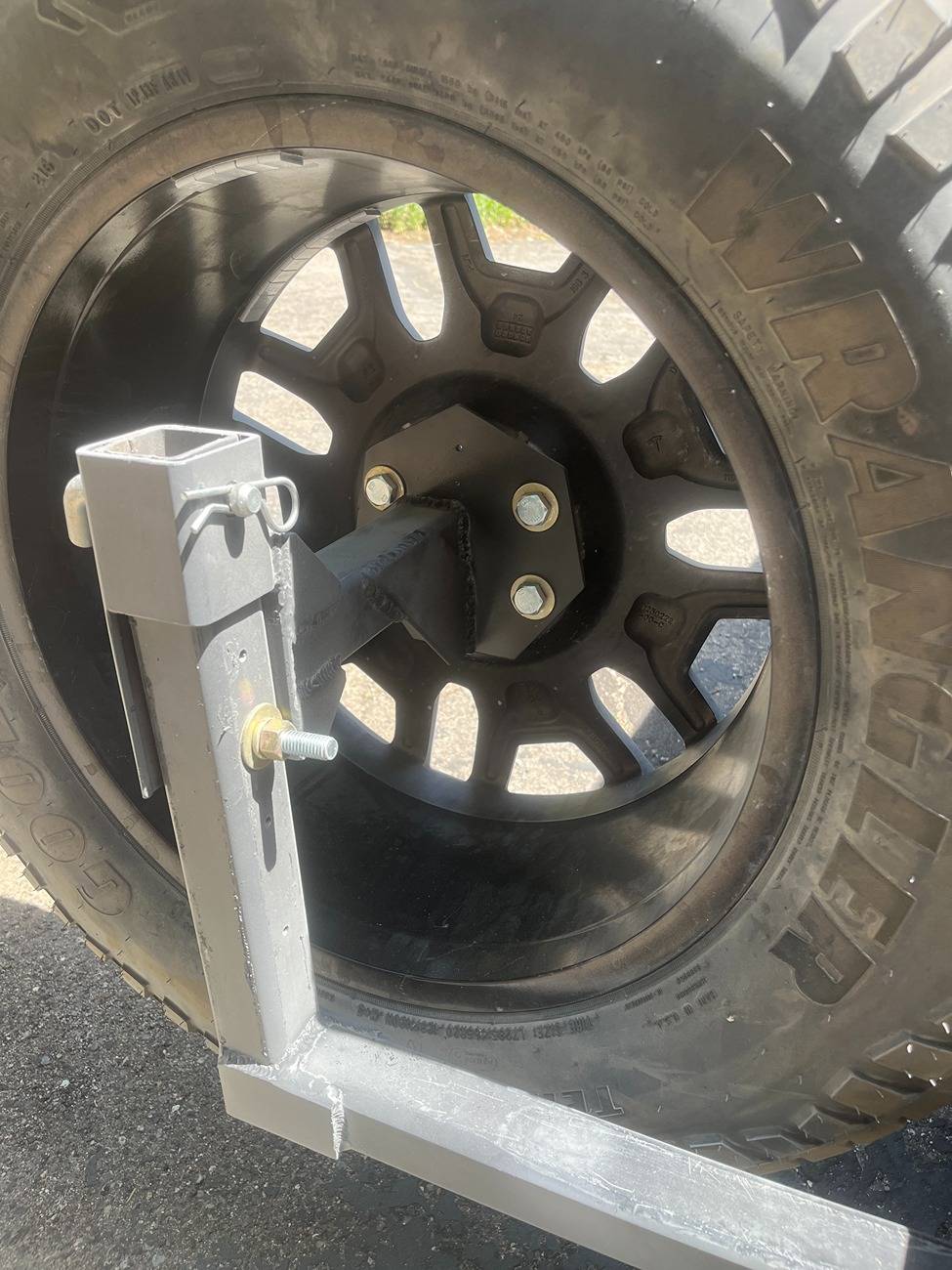
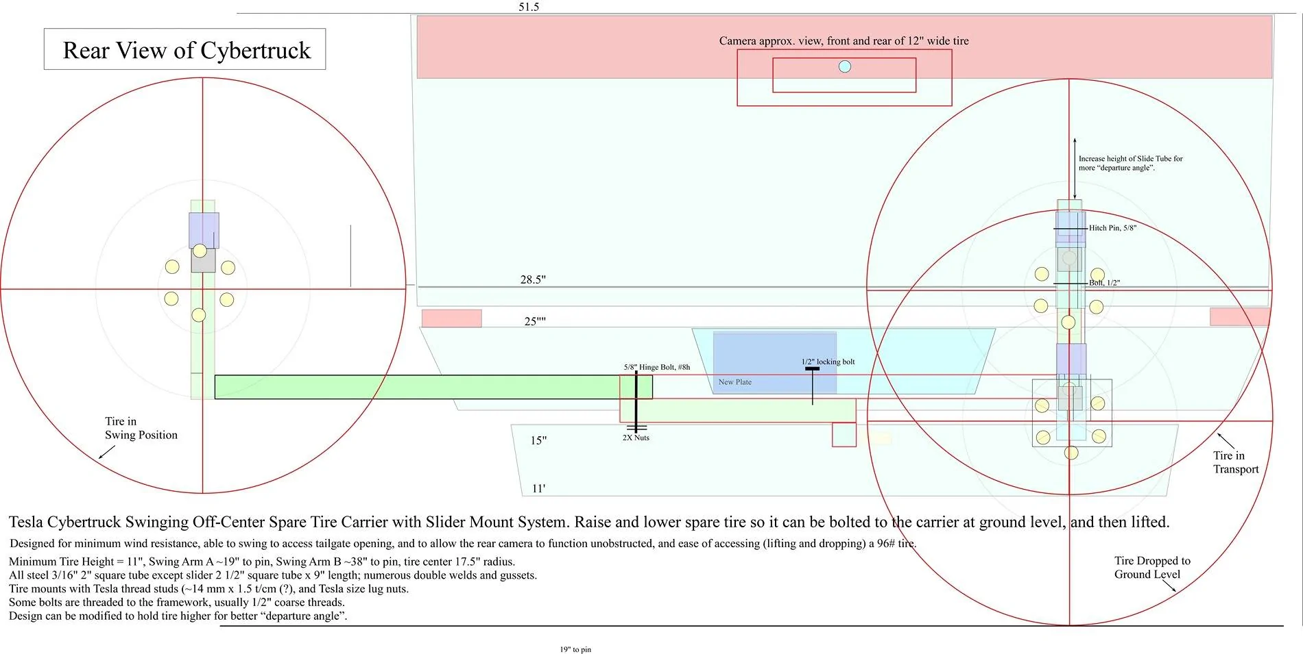
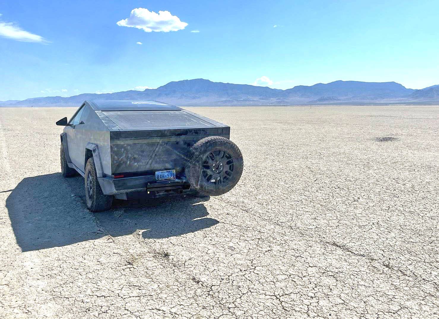
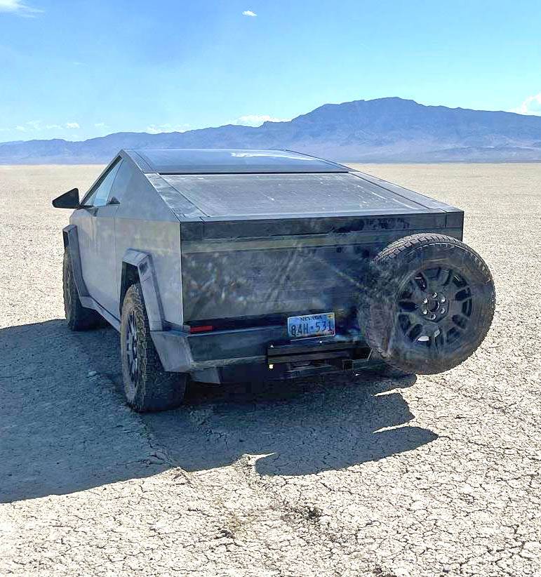
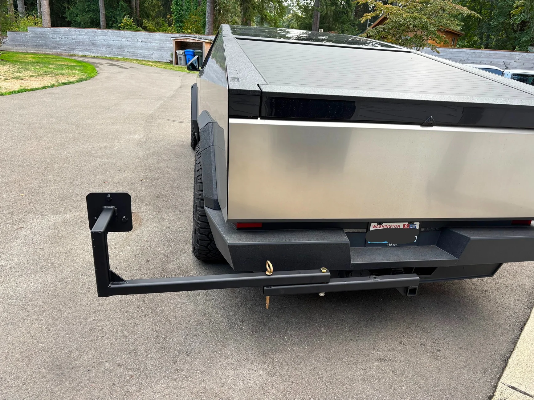
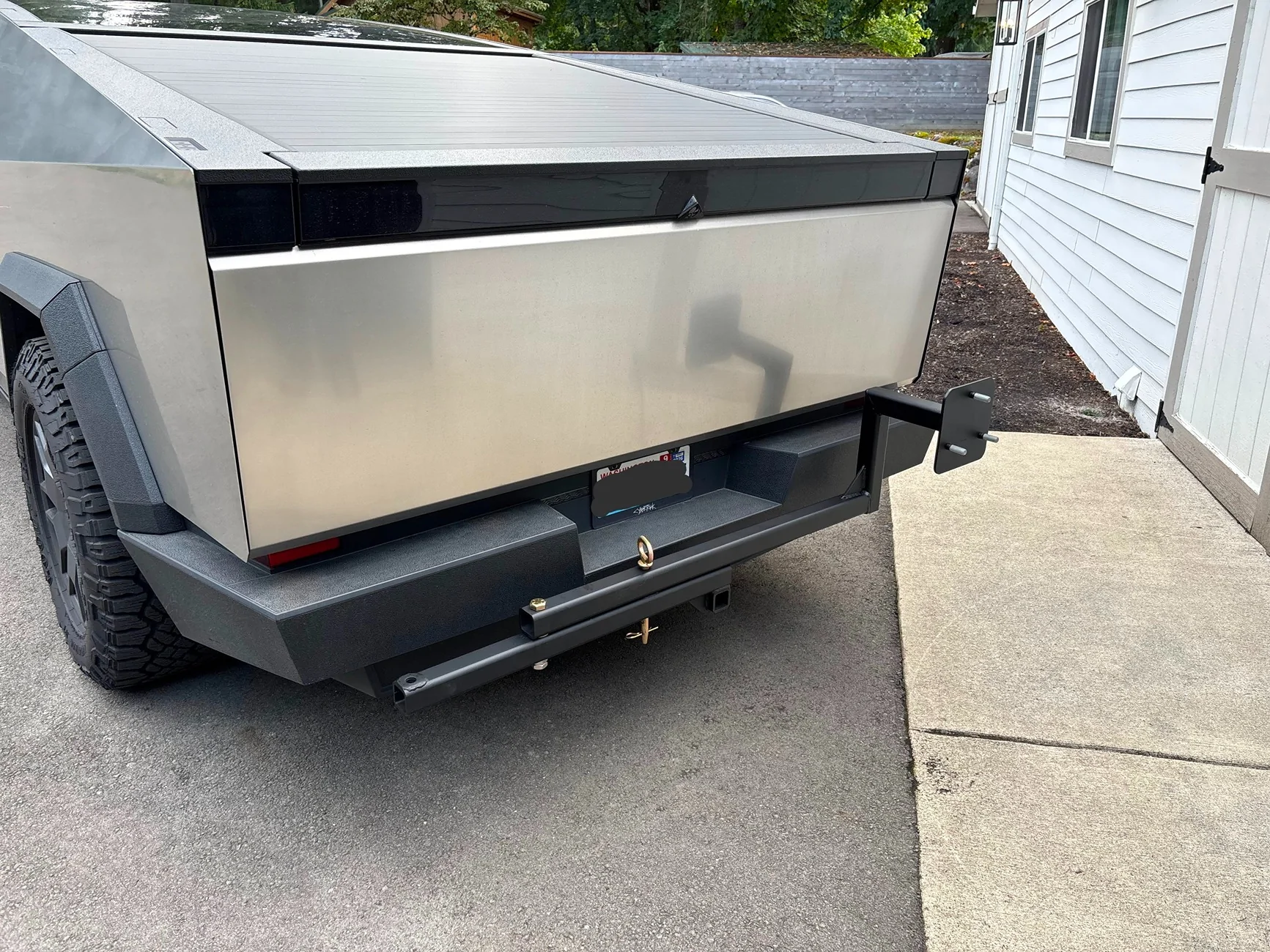
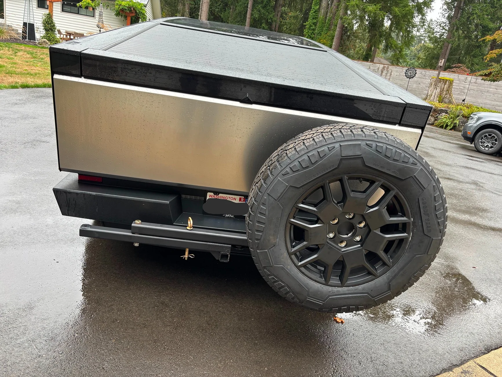
I have been perplexed how to carry a spare, so I built this. The criteria are to be strong, off-center so the camera works, low wind resistance, able to swing wide to use the tailgate, and easy to attach the tire without a heave-ho-hold-the-tire while you bolt it down. I used 2x2" square tube 3/16" thick for most, and a 9" piece of 2 1/2" square tube for the slider part. There are several gussets for reinforcements. This thing works great. I have attached quite a few photos with details, and a scaled diagram. I moved the license plate to the left, and the tail lights are not obstructed. FSD works, and when I back up there is a red dot/warning on the screen where the tire is located, and the back-up beeper sounds when I am in reverse.
I mount the wheel on a 7 sided polygon (septagon) shaped like the wheel, and threaded with Tesal-equivelent studs (14mm x 1.5 t/cm?). Also, the bolts are lugnuts for CT wheels.
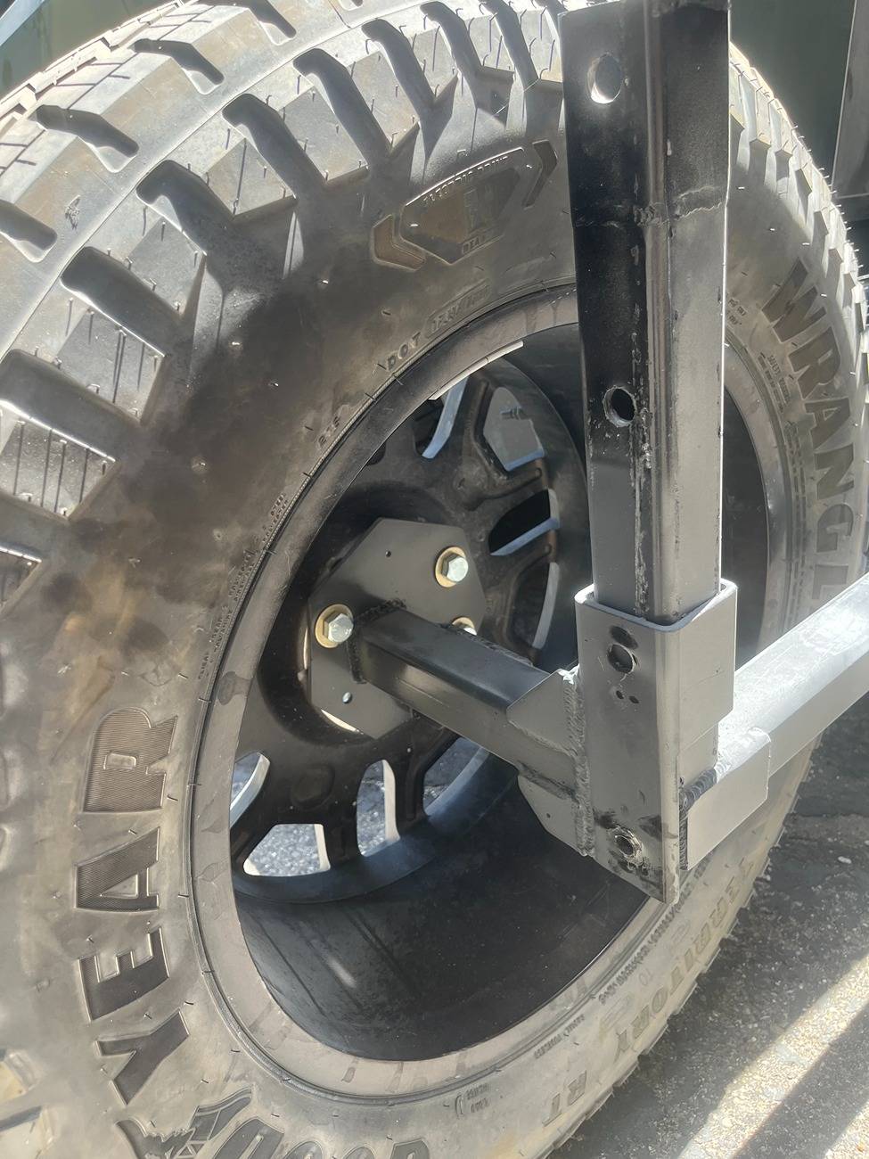
Images 1, 2, and 3 show viewpoints of the set up. Note that if the tailgate is accidentally opened, then it hits the tire, and not the steel rack.
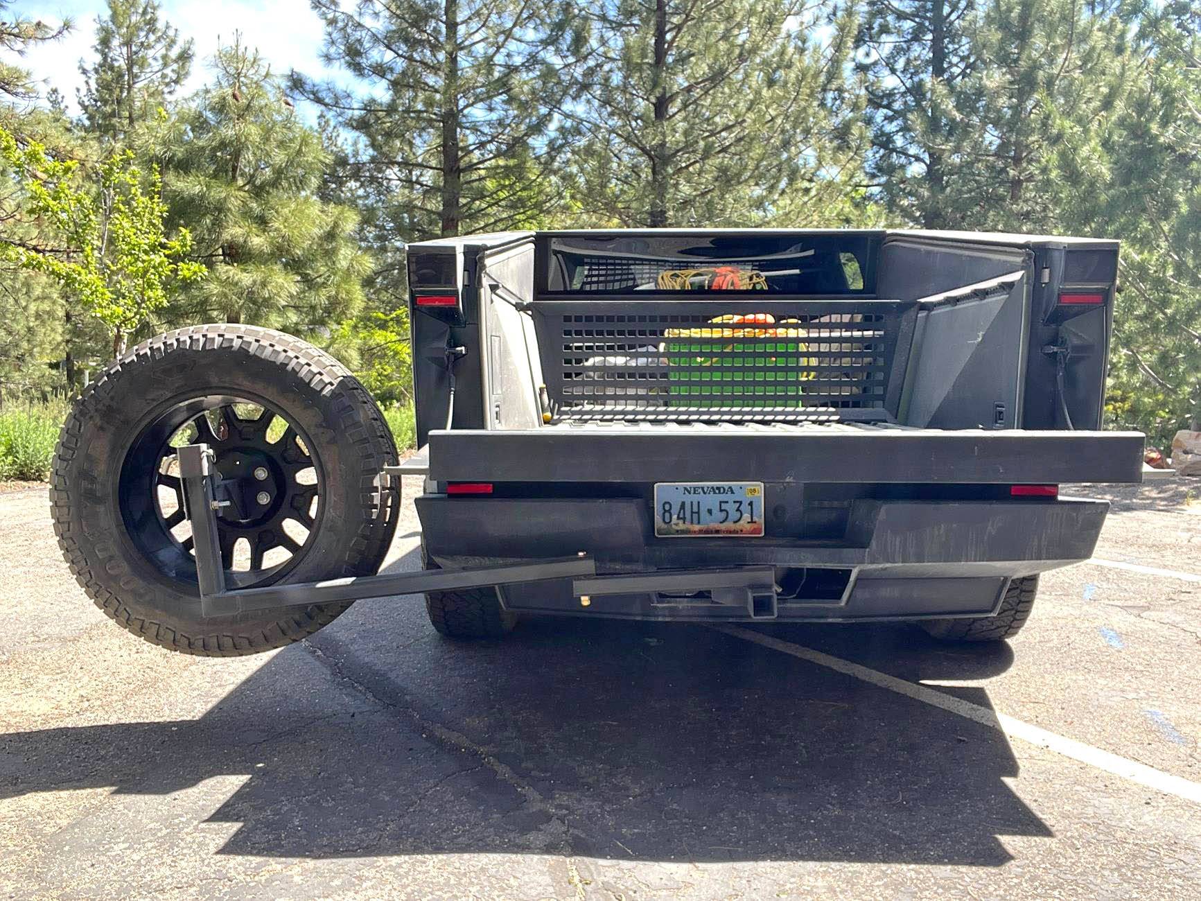
Image 4 shows the wheel swung to the side, and in the "up" position, before the slider is deployed.
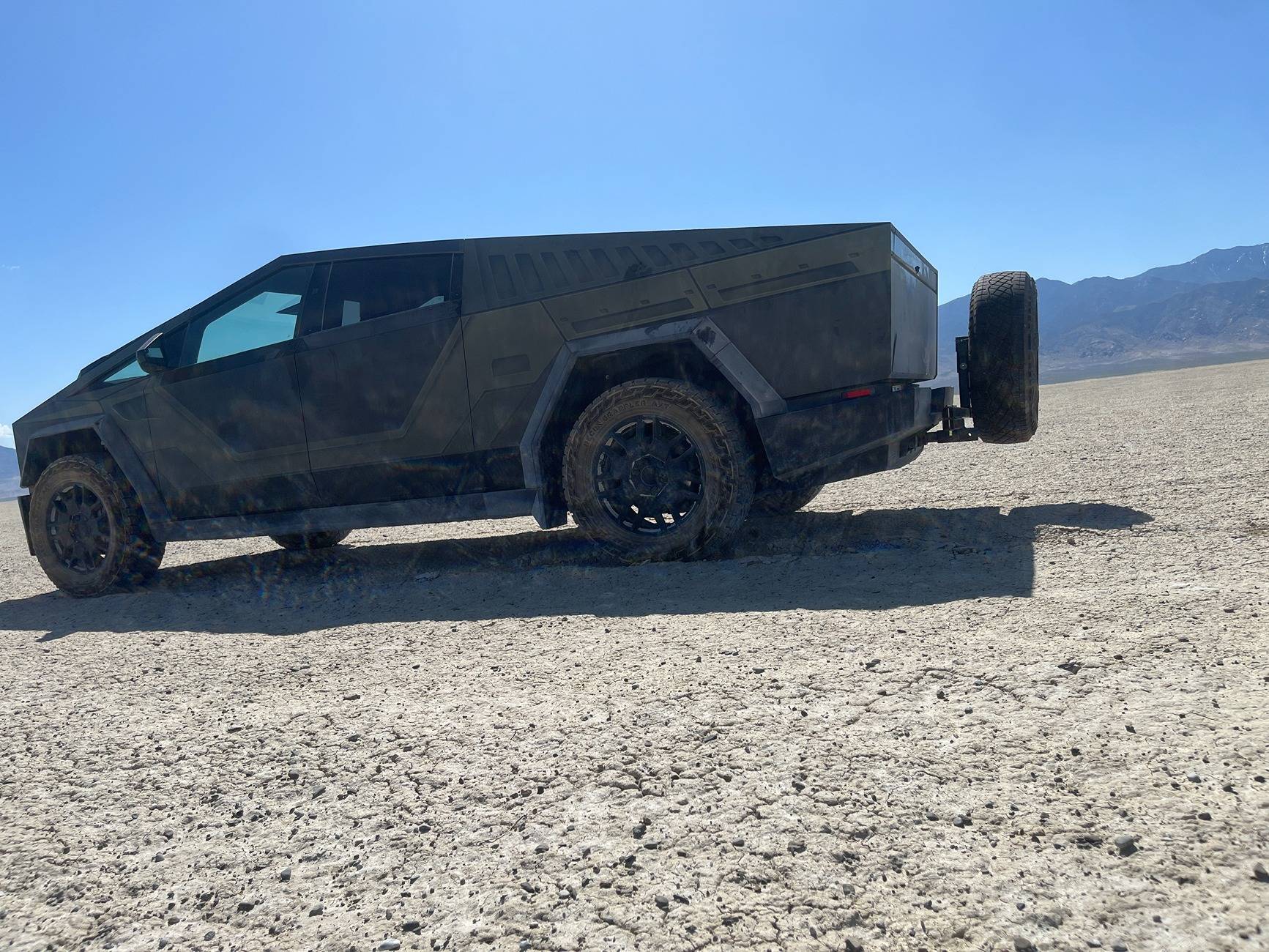
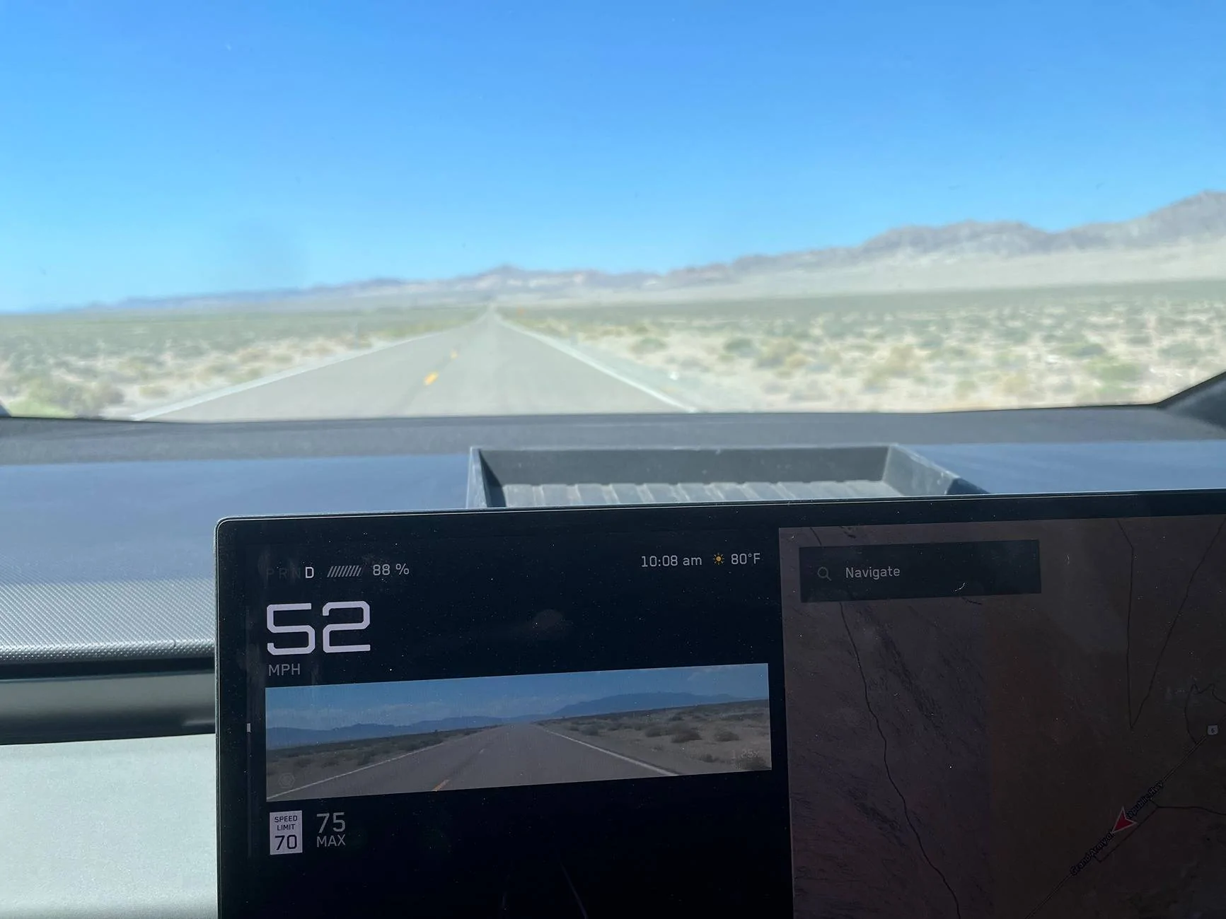
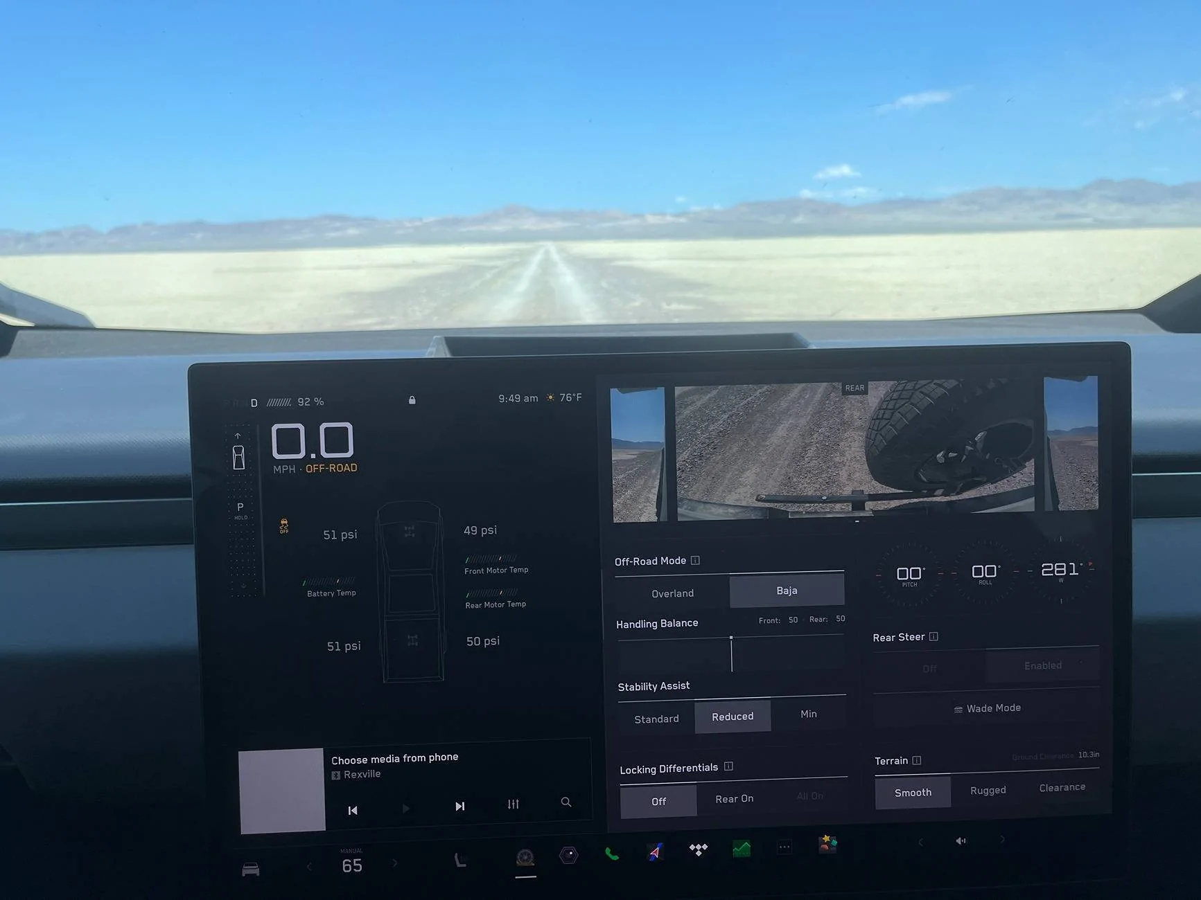
Image 5 shows the view through the rear view mirror on the pavement. Image 6 is the rearview mirror in Baja Mode, and the base of the tire is clearly visible for driving off of ramps.
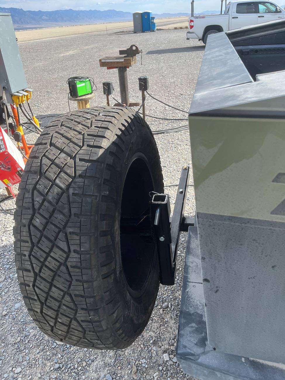
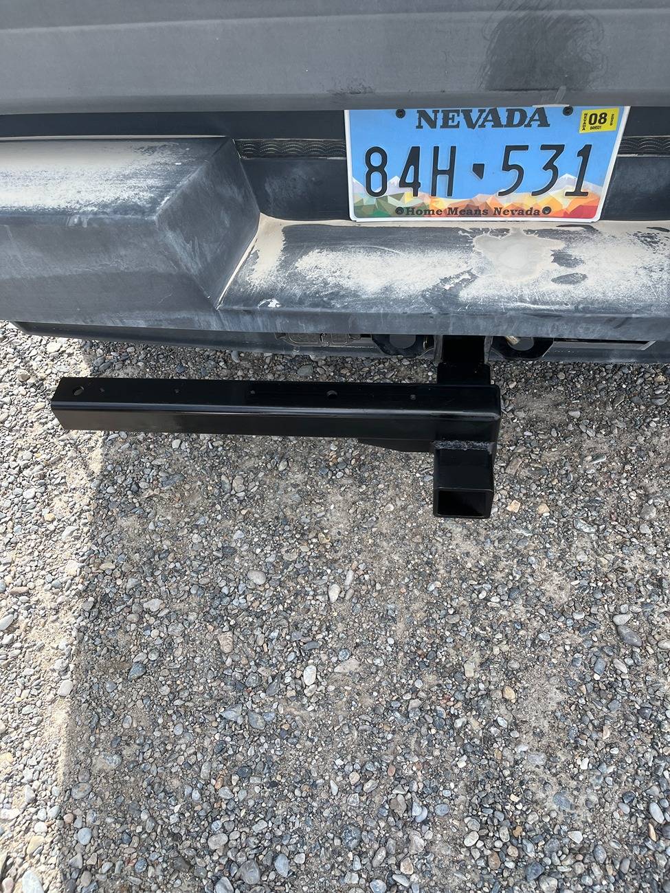
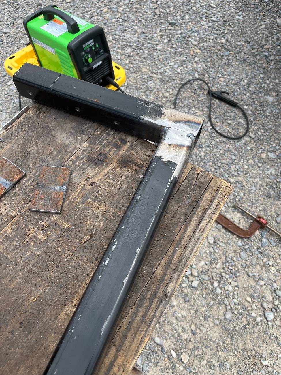
Image 7 is the lower support, welded to the trailer hitch attachment "extender". I bought the extender at Tractor Supply. Image 8 is the upper support - 38" long, with the upright support welded to it. The upper and lower supports are attached by a 5/8" bolt that acts as the hinge. There is an additional bolt used that keeps these two pieces from swinging apart while driving.
Images 9 and 10 show details of the slider piece that the wheel bolts to; this slides up and down for convenience, so that the wheel can be placed on the ground for bolting/unbolting to the tire rack.
Image 11 is the slider piece in the down position.
Image 12 is the diagram I used for the design.
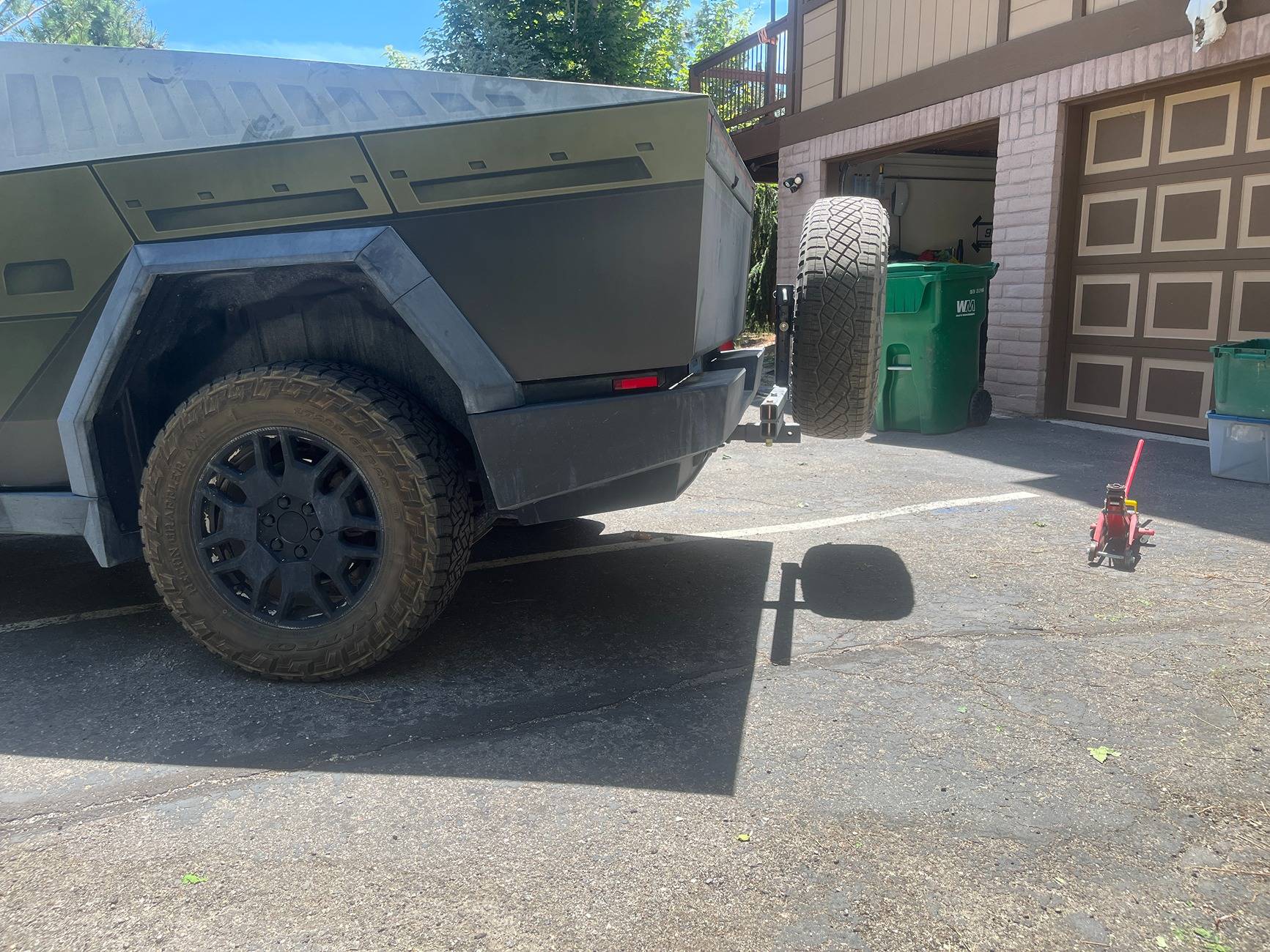
Image 13 is another photo of how the tire fits and looks from behind the vehicle.
I will probably now add a piece between the hitch and extender to keep these pieces from wriggling. It does not, due to the weight of the tire, but I do not like the fit. All hitches are this way, but I still do not like it.
Please enjoy the design. This is proto-type #1. Not perfect, but very functional.


OP
OP
Bobo_LaDouche
Well-known member
- Joined
- Nov 13, 2024
- Threads
- 8
- Messages
- 179
- Reaction score
- 268
- Location
- Carson City, Nevada
- Vehicles
- Cybertruck, Model 3
- Thread starter
- #24
Here is confirmation of the important dimensions, as measured on the rack:I actually went and got the steel square 3/16” tubing yesterday. I got 10 feet of the 2 x 2. And a foot of the 2 1/2 x 2 1/2. I forgot to get the plate. But that’s OK I don’t even have a spare tire yet!?.
Did you drill the bolt 1 inch from the end. It looks a little bit longer maybe a 1 1/2”?
I really like this design!
Now you have me curious as to what you’re going to change with it ?? ? Gen 2: Your thoughts??
The only thing I am going add to it, will be a welded plate with a hole to lock your tire with a cable. Attached to the main hitch so it doesn’t get stolen. Even if they do manage to get the bolt off they still can’t take the tire. Also plastic caps ends for the 2 x 2 holes, that I found on Amazon. Your thoughts??
I didn’t see any pictures of the umbrella holder?
When this is all said and done. I’m gonna try to find a Beastly tire cover for the back of it!?
Bolt hole for hinge is 1.0" from the end on both upper and lower swing arms.
Lower arm total length is 18.75"
Upper arm total length is 38.25"
Note that the upright 2x2 is welded on the outside of the upper arm, and is 16.25".
This all calculated perfect on the diagram, but when I spot welded and tested, I wanted to reduce the distance of the tire inward by 1" (less windage while driving, and enough clearance when swung open). I therefore moved the tire-flat-plate mount inboard of the center of the plate by 1".
Note - for those concerned about hitting bumps with the tire while off-roading, the upright mount could be made longer (4"?) as an option, so the tire could be lifted more on certain occasions. In this case the rear view mirror will not be affected, but the tail lights will be affected. The limit is so that accidental tailgate opening continues to hit the tire, and not the metal carrier. However I find "high" setting on Baja Mode to be just fine.
Last edited:
LarryASilva
Well-known member
- First Name
- Larry
- Joined
- Nov 3, 2023
- Threads
- 4
- Messages
- 63
- Reaction score
- 82
- Location
- SF Bay Area
- Vehicles
- Boxster, MiniVan
- Occupation
- Retired
Great work and thanks for sharing.I have been perplexed how to carry a spare, so I built this. The criteria are to be strong, off-center so the camera works, low wind resistance, able to swing wide to use the tailgate, and easy to attach the tire without a heave-ho-hold-the-tire while you bolt it down. I used 2x2" square tube 3/16" thick for most, and a 9" piece of 2 1/2" square tube for the slider part. There are several gussets for reinforcements. This thing works great. I have attached quite a few photos with details, and a scaled diagram. I moved the license plate to the left, and the tail lights are not obstructed. FSD works, and when I back up there is a red dot/warning on the screen where the tire is located, and the back-up beeper sounds when I am in reverse.
I mount the wheel on a 7 sided polygon (septagon) shaped like the wheel, and threaded with Tesal-equivelent studs (14mm x 1.5 t/cm?). Also, the bolts are lugnuts for CT wheels.
Images 1, 2, and 3 show viewpoints of the set up. Note that if the tailgate is accidentally opened, then it hits the tire, and not the steel rack.
Image 4 shows the wheel swung to the side, and in the "up" position, before the slider is deployed.
Image 5 shows the view through the rear view mirror on the pavement. Image 6 is the rearview mirror in Baja Mode, and the base of the tire is clearly visible for driving off of ramps.
Image 7 is the lower support, welded to the trailer hitch attachment "extender". I bought the extender at Tractor Supply. Image 8 is the upper support - 38" long, with the upright support welded to it. The upper and lower supports are attached by a 5/8" bolt that acts as the hinge. There is an additional bolt used that keeps these two pieces from swinging apart while driving.
Images 9 and 10 show details of the slider piece that the wheel bolts to; this slides up and down for convenience, so that the wheel can be placed on the ground for bolting/unbolting to the tire rack.
Image 11 is the slider piece in the down position.
Image 12 is the diagram I used for the design.
Image 13 is another photo of how the tire fits and looks from behind the vehicle.
I will probably now add a piece between the hitch and extender to keep these pieces from wriggling. It does not, due to the weight of the tire, but I do not like the fit. All hitches are this way, but I still do not like it.
Please enjoy the design. This is proto-type #1. Not perfect, but very functional.
Cybertruck 1974
Well-known member
- Joined
- Dec 15, 2019
- Threads
- 51
- Messages
- 1,197
- Reaction score
- 1,628
- Location
- Everywhere
- Vehicles
- Cybertruck, H2, Samurai, Ford Transit, Chevy Silverado EV, Jaguar, Corvette, M38
2x4 stock with one pivot point will make it stronger. good work.
HickoryGoose
Well-known member
- First Name
- Gilles
- Joined
- Jun 18, 2020
- Threads
- 0
- Messages
- 63
- Reaction score
- 94
- Location
- Fall City, WA
- Vehicles
- 2024 FS AWD CT, 2018 M3DM
- Occupation
- Clinical Scientist
I got mine built. We simplified the design a bit and added wedges to reduce motion while driving. Need heavy hammer to help get it off but worth it. Had it professionally power coated (already scratched it) so I'm into it with materials around $450. Very happy with how it turned out. With the rear view zoomed to 1.1, I can see a little bit of the tire, enough to know it's there. May replace the bumpers at some point. UP has a rear bumper with an integrated spare holder - would add that if I do go that route.
Thank you Bobo for sharing.
Thank you Bobo for sharing.
hemiarch
Well-known member
- First Name
- Ace
- Joined
- Jan 22, 2025
- Threads
- 123
- Messages
- 8,720
- Reaction score
- 10,125
- Location
- Arizona
- Vehicles
- 2024 foundation AWD, 2024 model x
- Occupation
- Trauma Surgeon
That’s awesome!!I got mine built. We simplified the design a bit and added wedges to reduce motion while driving. Need heavy hammer to help get it off but worth it. Had it professionally power coated (already scratched it) so I'm into it with materials around $450. Very happy with how it turned out. With the rear view zoomed to 1.1, I can see a little bit of the tire, enough to know it's there. May replace the bumpers at some point. UP has a rear bumper with an integrated spare holder - would add that if I do go that route.
Thank you Bobo for sharing.
Gaximus
Well-known member
- Joined
- Jun 22, 2024
- Threads
- 24
- Messages
- 1,491
- Reaction score
- 2,347
- Location
- Mead, CO
- Vehicles
- CyberBeast, Model 3, Jeep Wrangler, Yamaha R6
- Occupation
- Software Developer
This is awesome, and I don’t mean to be critical, but it bothers me that it’s not centered, and if its not centered why not have it open to the side it’s closest to?
Sponsored
Similar threads
- Replies
- 57
- Views
- 6,385