cvalue13
Well-known member
- Joined
- Aug 17, 2022
- Threads
- 74
- Messages
- 7,153
- Reaction score
- 13,769
- Location
- Austin, TX
- Vehicles
- F150L
- Occupation
- Fun-employed
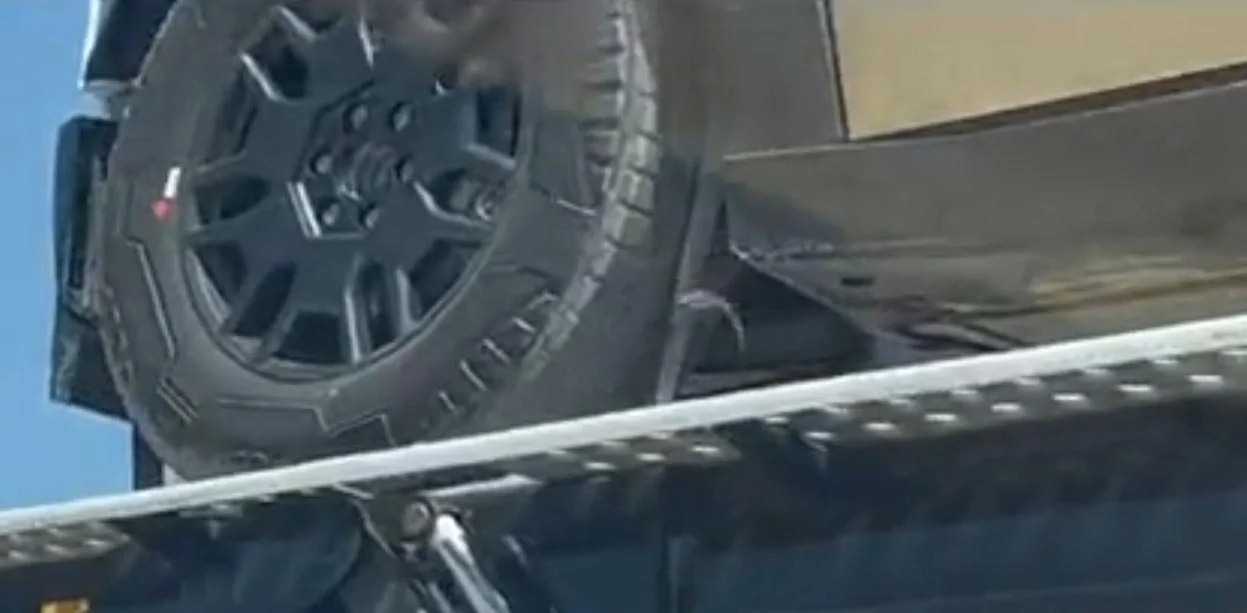
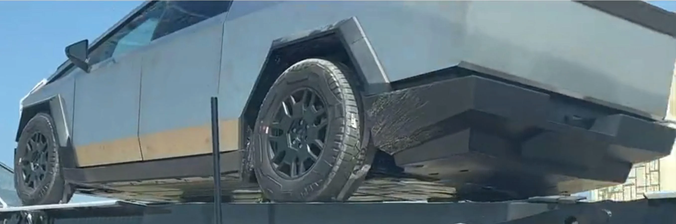
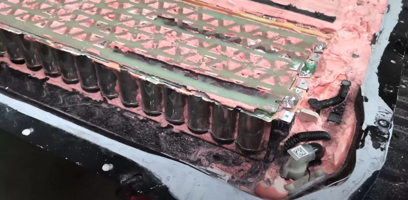
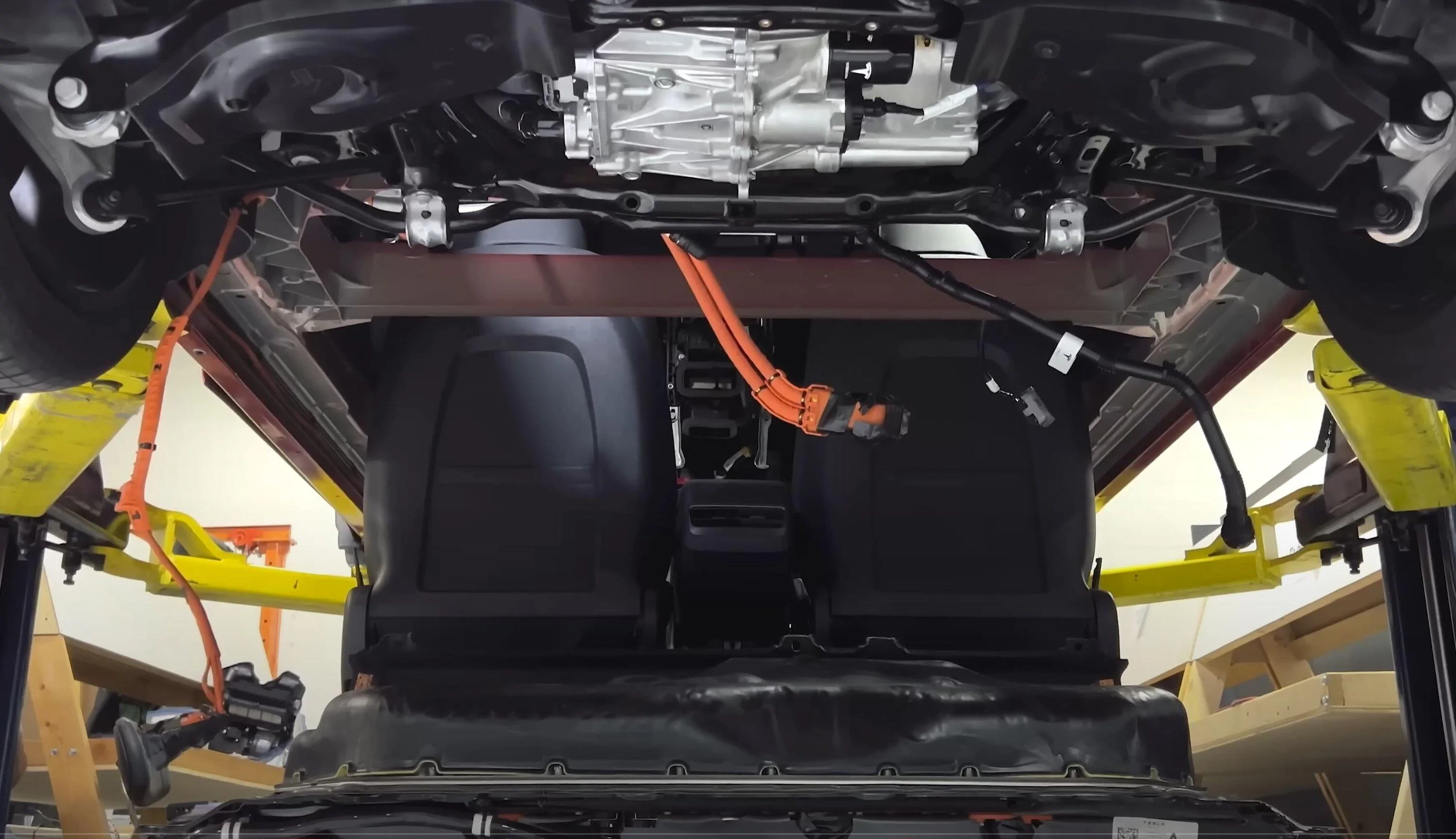
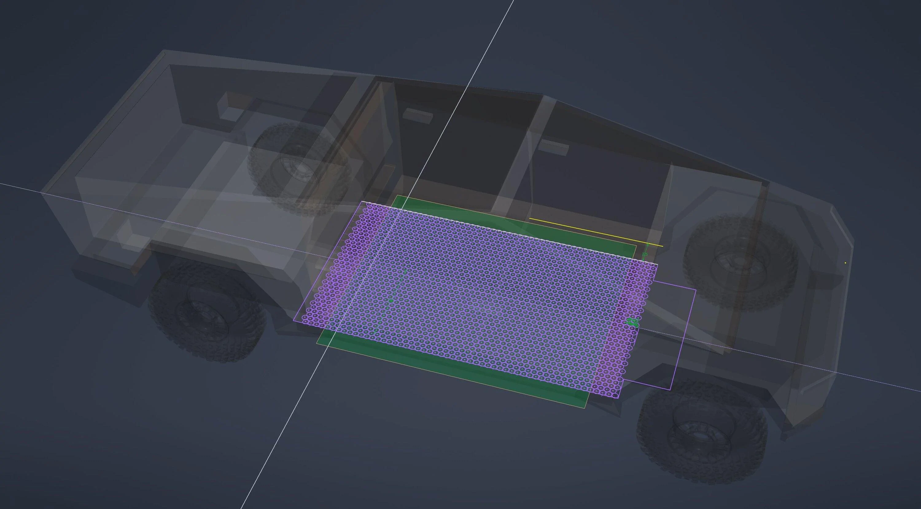
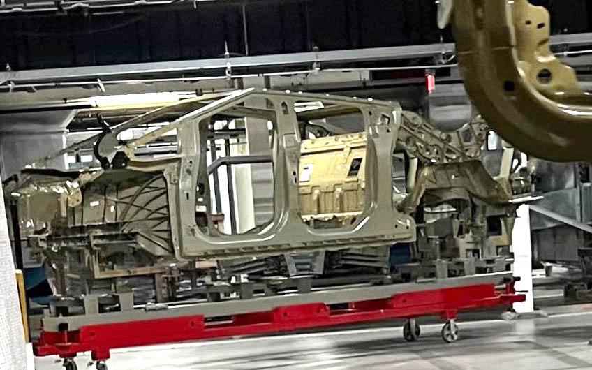
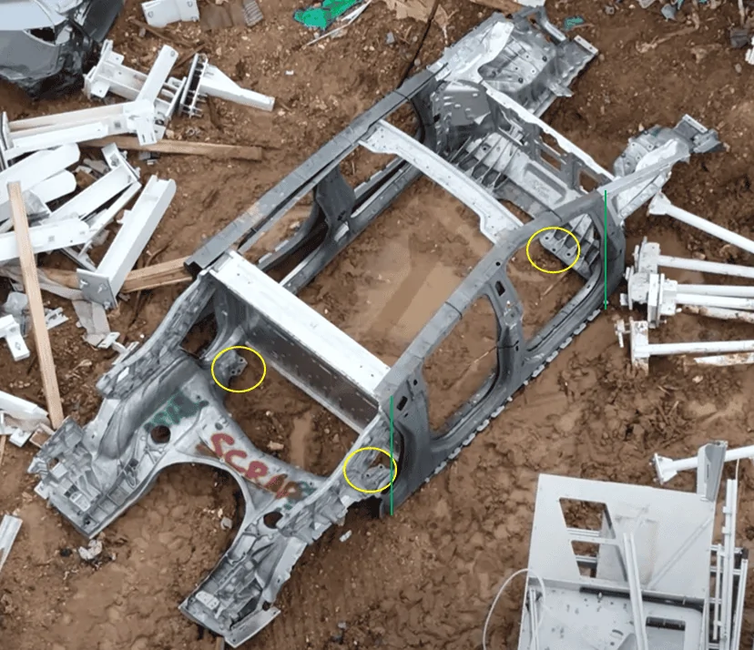
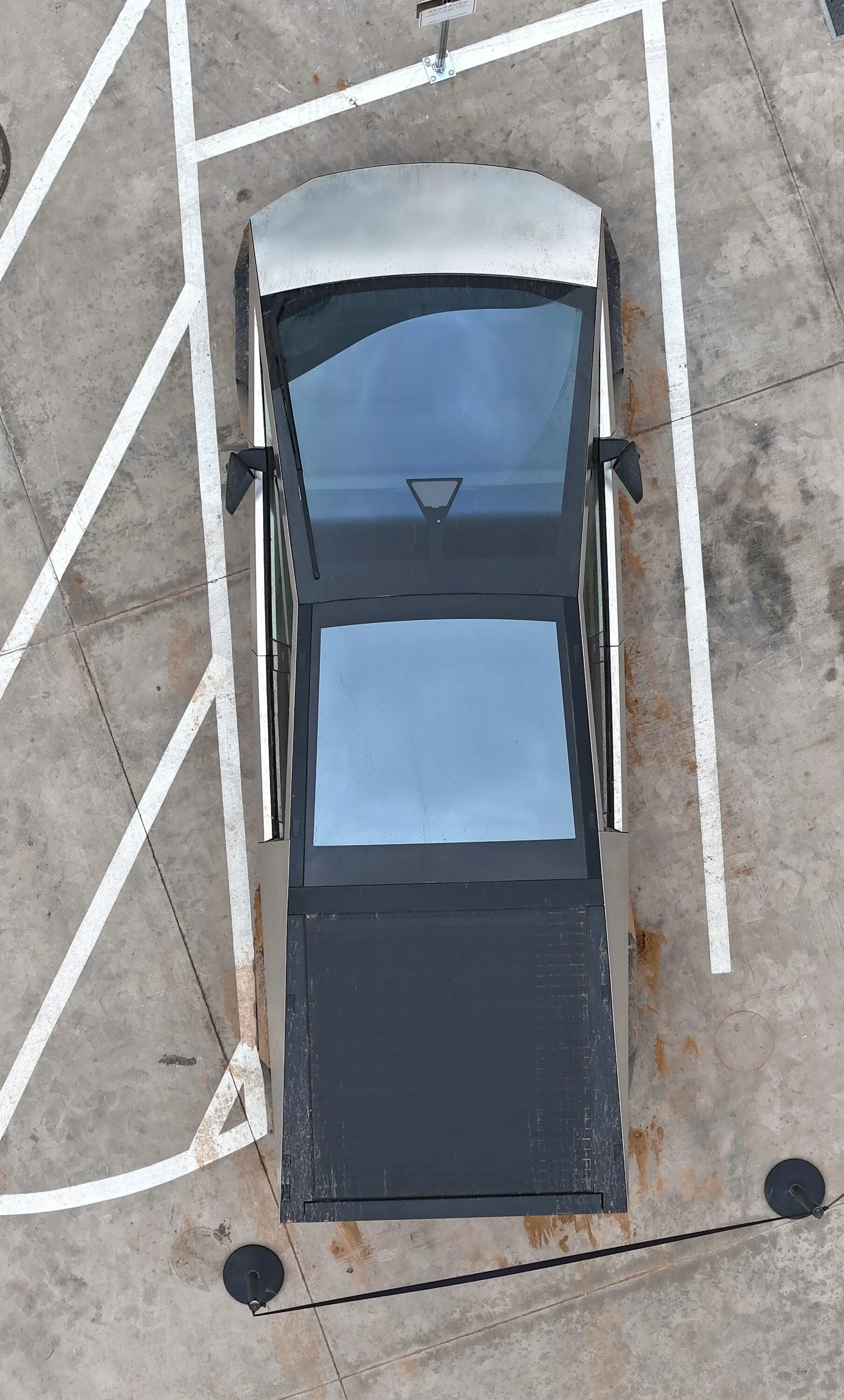
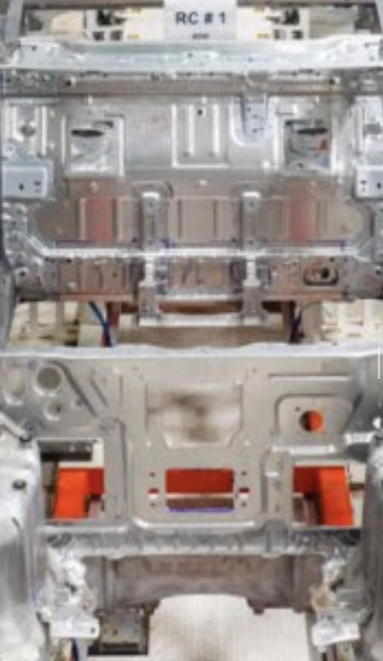
by chance, just today, there’s a flyover of an upside down BIBThis leads me to another question though, and that is if the pack is attached to the rear bulkhead,
Also coincidentally, this upside down shot of the rear raises a question I was gonna ask earlier but didn’t want to muddle the convo - but here it is again:
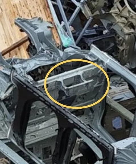
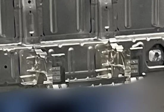
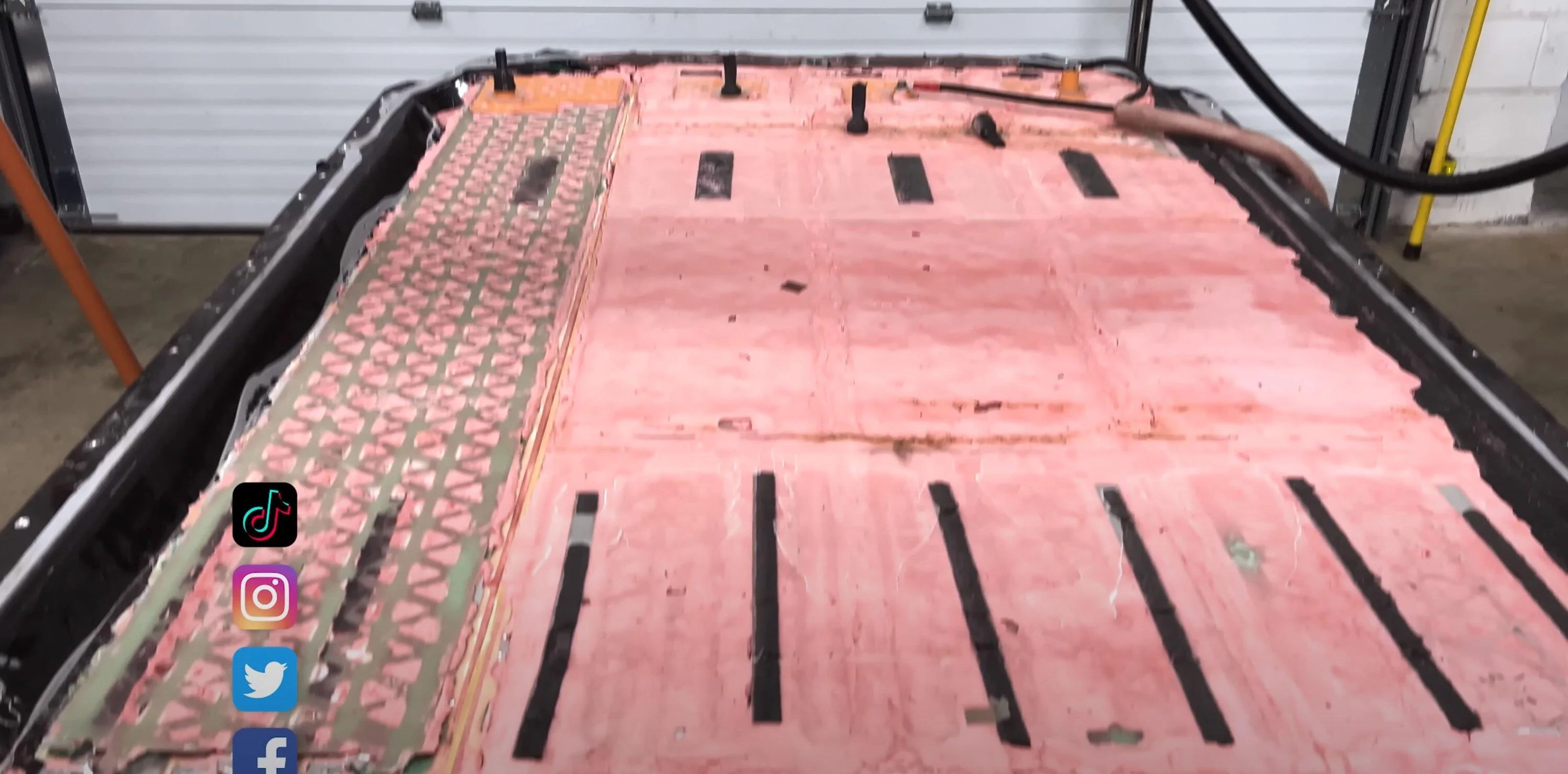
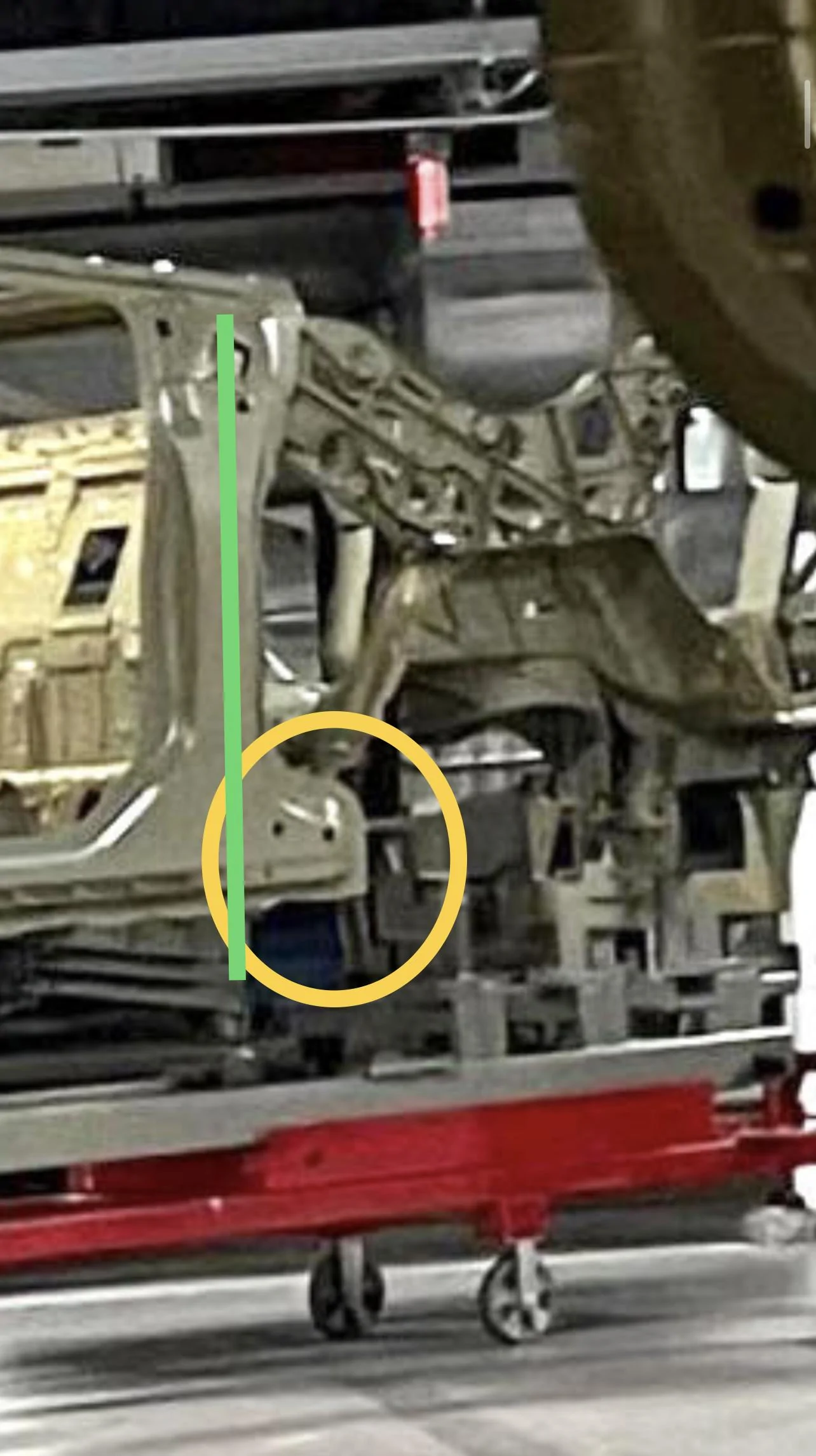
what’s the deal with that bracket?
and relatedly, it looks like there’s a space between the top of the pack and the floorboard about the depth of that bracket?
Sponsored