Metalwolftensei
New member
- First Name
- Nate
- Joined
- Jan 27, 2026
- Threads
- 0
- Messages
- 2
- Reaction score
- 2
- Location
- Pennsylvania
- Vehicles
- Cybertruck Foundation, Model Y Juniper
- Occupation
- Military
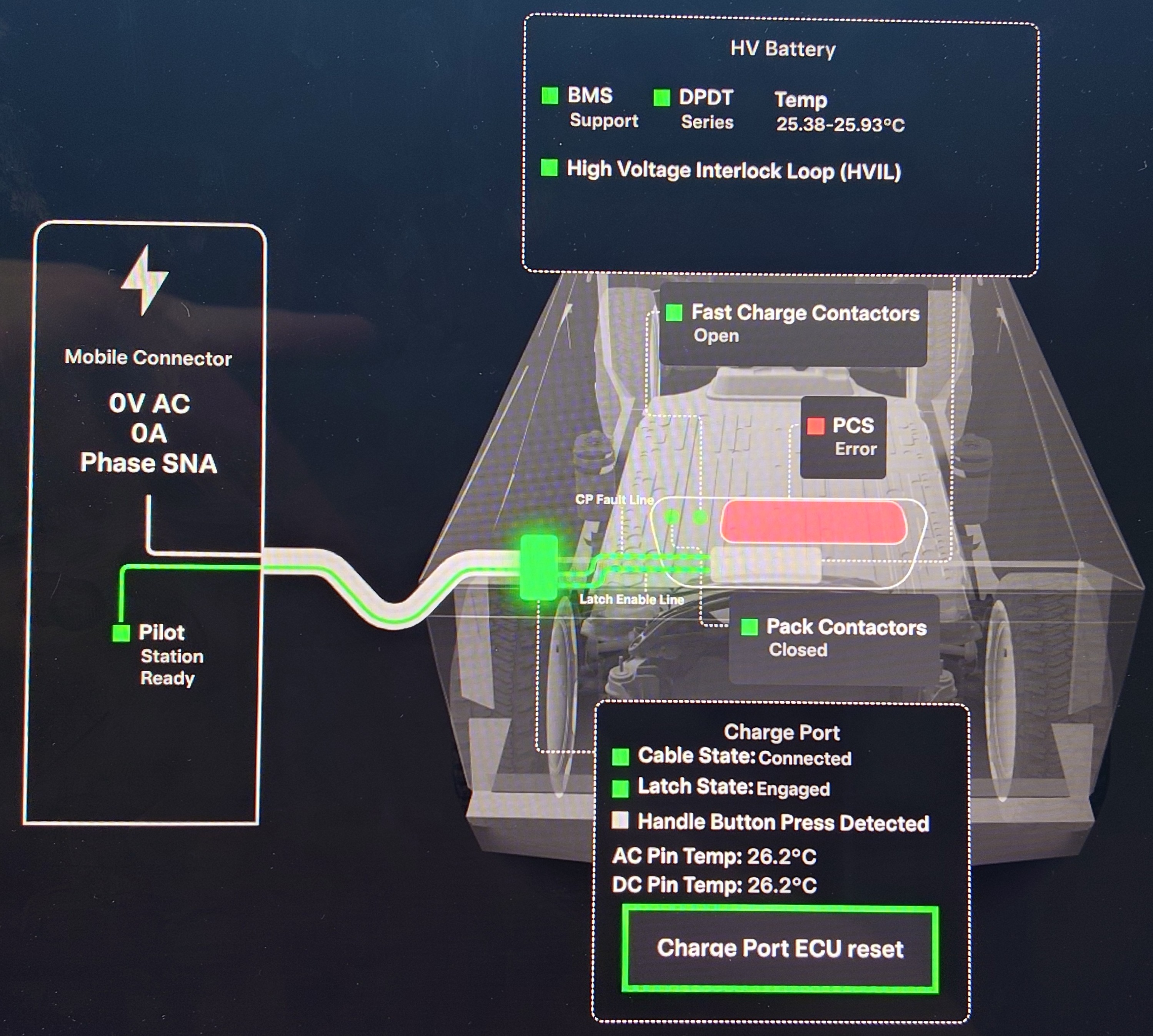
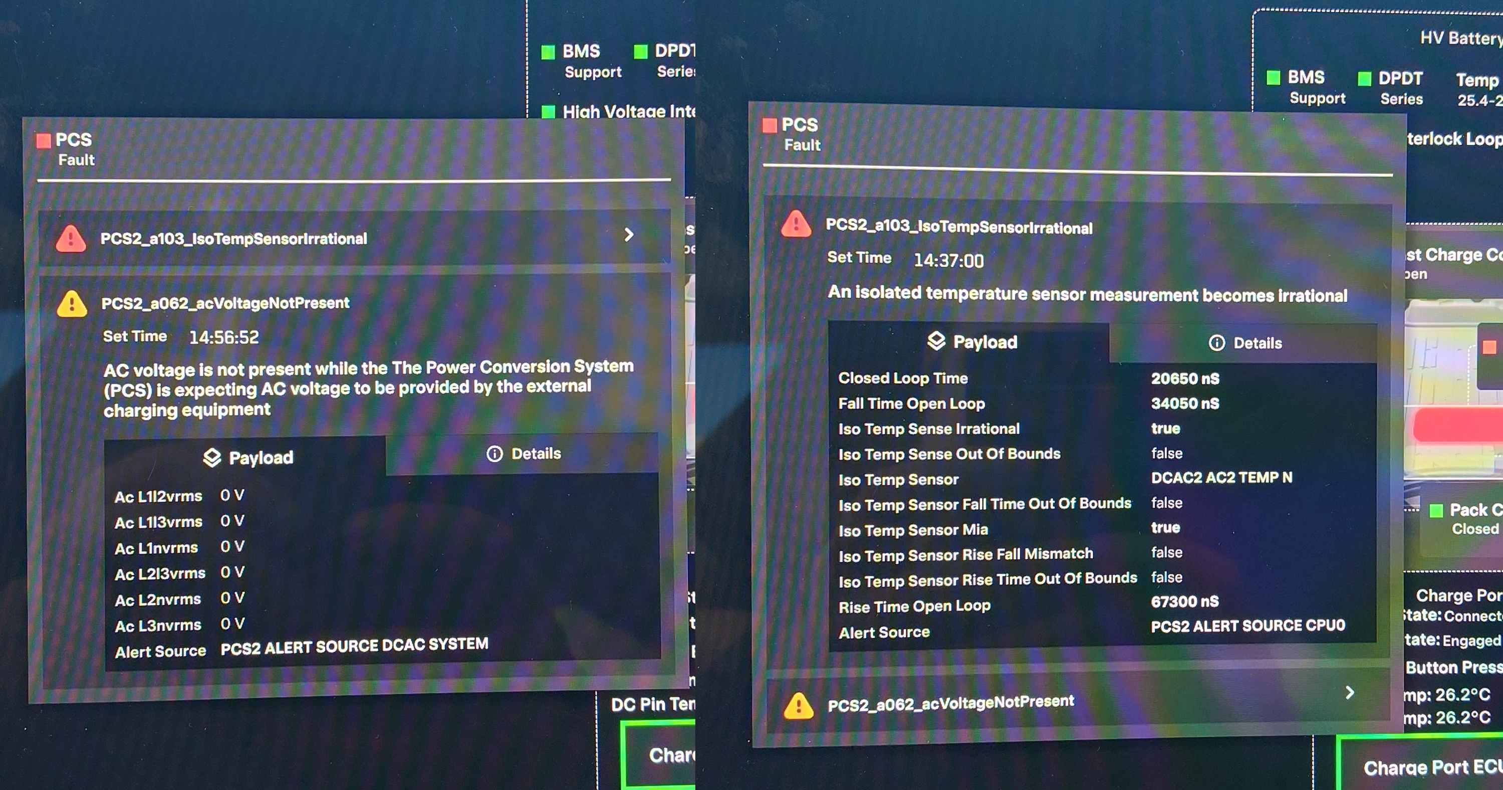
Is there a way to see if the PCS is failing if your household setup limits you to 24 amps? Since ownership I have always limited my charging to +24..
Sponsored