Home Charging System / Charger Kit

ajdelange

Well-known member
First Name
A. J.
Joined
Dec 8, 2019
Threads
4
Messages
3,213
Reaction score
3,403
Location
Virginia/Quebec
Vehicles
Tesla X LR+, Lexus SUV, Toyota SR5, Toyota Landcruiser
Occupation
EE (Retired)
Country flag
Sometimes they put them at the bottom. They did that in some construction I had done in Quebec. You should have seen the look on the electrician's face when I told him that in the states they usually put the main breaker at the top and asked him if the electricity could flow up as well as down.

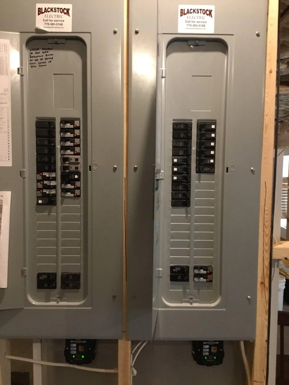
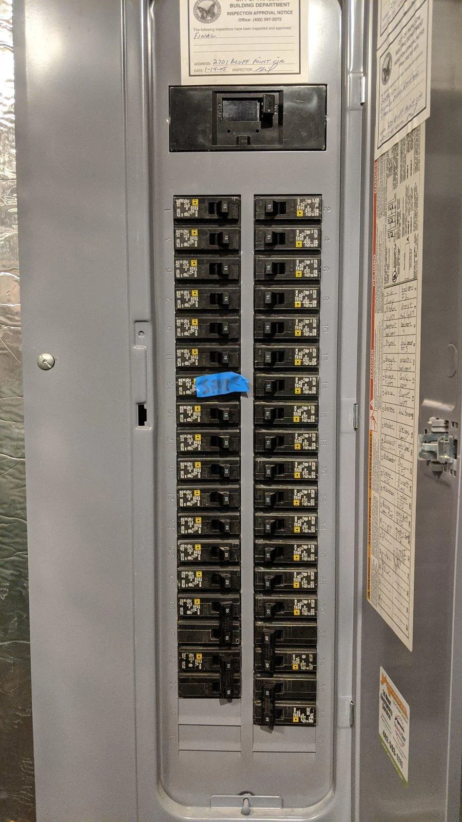
But it appears that you have what would be referred to as a 200 Amp service. While there is only 1 toggle on this main breaker labeled 200 we know that it has 2 poles so this service is capable of supplying 400 pole amperes. It looks as if you have the following branch breakers installed

15
20
25
25
40
40
20
20
20
20
20
15
15
20
20
30
30
15
15

These total 425 pole amperes. A Gen 3 HPWC comissioned for the maximum 48 amperes of charging is a dual phase 60 ampere load equal to 120 pole amperes. Adding that to 425 would give 545 pole amperes which is well less than 800 so you should be OK. In fact you would be able to add a second for a total of 665.
Sponsored


ajdelange

Well-known member
First Name
A. J.
Joined
Dec 8, 2019
Threads
4
Messages
3,213
Reaction score
3,403
Location
Virginia/Quebec
Vehicles
Tesla X LR+, Lexus SUV, Toyota SR5, Toyota Landcruiser
Occupation
EE (Retired)
Country flag
No problem. But to give an idea of the flexibility the new Gen 3's will give lets note that there is plenty of room in your panel to install 4 dual pole 60A breakers to which you could wire 4 Gen 3 HPWC. Each of those HPWC can draw up to 48 amps per pole so they are 96 pole-ampere loads. Four of them adds 384 pole-amperes to your panel's load count which, with the 425 you already have, gets you to a total of 425 + 384 = 809 pole-amps. The is just over the 800 pole ampere limit (which isn't really a limit - it just seems to be a number everyone appears to be comfortable with) but only slightly. An inspector should be happy but if he isn't you could always promise to set the total draw of the HPWC ensemble to a lower number which gets the total to under 800. This is something you will be able to do when the firmware is complete (new firmware will be downloaded to units bought today over WiFi). Let's say you reduce the ensemble draw to 364 pole amperes. That's 182 A at 240 which amounts to 45.5 amps per car if 4 tried to charge at once. A more likely scenario would be that of subsequent arrival. The first three arrivals would get 48 A each and the fourth the remaining 38. As soon as any one of the early arrivals completes or as soon as you lower the charging rate for one of those the freed current goes to the last to arrive.

Summary; you will have lots of flexibility.
 

Frank W

Well-known member
First Name
Frank
Joined
Dec 6, 2019
Threads
28
Messages
374
Reaction score
443
Location
White, Georgia
Vehicles
2007 Toyota Tacoma
Occupation
Retired Army 1975-1997
Country flag
This conversation had me thinking about my own situation and while I was told that I have a 400 Amp service at my house and I assumed that I had plenty of space for charging a EV however a question came up. I have whole house surge protectors installed and am I right in thinking that the main shut off would be each of them at the lowest breaker which are for the protectors below the box? Also any recommendations going forward would be appreciated. I have no real knowledge of electric.
Tesla Cybertruck Home Charging System / Charger Kit B31437D5-7CEA-45C4-A28E-E191E16C5B5B
 

ajdelange

Well-known member
First Name
A. J.
Joined
Dec 8, 2019
Threads
4
Messages
3,213
Reaction score
3,403
Location
Virginia/Quebec
Vehicles
Tesla X LR+, Lexus SUV, Toyota SR5, Toyota Landcruiser
Occupation
EE (Retired)
Country flag
I'll have to take your word for it that the service is 400 A (800 phase-amps) and the fact that you have 2 panels suggests this is likely. It doesn't appear that these panels are very heavily populated so there should be plenty of capacity for 3 or 4 HPWC.

I can't tell from the photo if those breakers at the bottom are the main breakers for these panels or for some other load. If they are 200 A breakers then it is likely they are. If not there would have to be breakers some where else (wherever the service entrance is) for that function.
 

Frank W

Well-known member
First Name
Frank
Joined
Dec 6, 2019
Threads
28
Messages
374
Reaction score
443
Location
White, Georgia
Vehicles
2007 Toyota Tacoma
Occupation
Retired Army 1975-1997
Country flag
I'll have to take your word for it that the service is 400 A (800 phase-amps) and the fact that you have 2 panels suggests this is likely. It doesn't appear that these panels are very heavily populated so there should be plenty of capacity for 3 or 4 HPWC.

I can't tell from the photo if those breakers at the bottom are the main breakers for these panels or for some other load. If they are 200 A breakers then it is likely they are. If not there would have to be breakers some where else (wherever the service entrance is) for that function.
Tesla Cybertruck Home Charging System / Charger Kit 8F6572FE-81B9-4641-A4AB-CFDFE4A78DB9


Thanks AJ. I found it outside and itā€™s good that I know that now. Your answer helped. Itā€™s a new house so I hadnā€™t got to this before now.
 
Last edited:


Bill906

Well-known member
Joined
Mar 21, 2020
Threads
4
Messages
1,386
Reaction score
3,229
Location
Wisconsin
Vehicles
Jeep
Country flag
I think the problem here is that electricity can get complicated. Some people learn how it actually works and others just go by simplified rules or sayings they've heard. An example of this is on the explanation behind getting an electrical shock. Instead of having a firm grasp of how voltage, current and resistance effect each other someone might just say "It's the amps that kill you" not taking into account it's the voltage and resistance of the body that determine the amps. For many, simplifying how electricity works is just fine most of the time, but not always. For example, someone who doesn't know any better may be afraid to touch their 12V car battery terminals because the battery says it can supply 500A. All they know is itā€™s the amps that kill you.

I started saying people either fully know the fundamentals of electricity or they rely on shortcuts. I should say there is another possibility, that someone once understood the true fundamentals, but has used the shortcut tools so often they forget the fundamentals.


I think the ā€œphase ampsā€ term AJ created is just a simplified tool to help understand the math but does not actually exist in the circuit.

Typically a 200 A panel (which is 400 phase amps as I like to call them as there are two phases)
*Underline added for emphasis

I did a quick google search of "phase amps" and only found hits related to three-phase power.

From my first post on the subject I said I didn't want to get into the argument of if a center tapped winding on a transformer creates a two-phase system, but here we are. A typical residential house is a single-phase service. Center-tapping a transformer winding and looking at half of the winding upside down does not create a second phase. Definition of single phase:

In electrical engineering, single-phase electric power is the distribution of alternating current electric power using a system in which all the voltages of the supply vary in unison.


From a different article:

Since the two phasors do not define a unique direction of rotation for a revolving magnetic field, a split single-phase is not a two-phase system.

If you are still insistent on calling a center tapped transformer a two-phase system I have a question. If a transformer winding with three taps creates a two phase system, can you create a three-phase system from a transformer winding with 4 taps? (The answer is NO).

A BEV charger installed in a residential setting would be a single-phase device.

Even in an actual multi-phase system you donā€™t add up the phase currents. A three-phase induction motor with an FLA (full load amp) rating of 30A would have 30A measured in leg 1, 30A measured in leg 2 and 30A measured in leg 3 assuming the motor was running at rated speed and at full load. Using the ā€œphase ampā€ term I guess that would be a 90 phase amp motor?


If you do a true circuit analysis of a typical residential 200A service, you will not find 400A anywhere in the circuit. Using an ammeter you will not measure 400A anywhere in the circuit.

If the system is balanced there is no current in the neutral. The current comes in one hot goes through both loads and leaves out the other hot. Itā€™s a series circuit. (After taking the picture I realized I forgot to label 0 amps in the neutral.). If there is no current flowing through the neutral it can be considered not there.

Tesla Cybertruck Home Charging System / Charger Kit 1589678437946


On an unbalanced system some of the current is split between the neutral and the other hot. But it's the same current. 200A comes in, half of if goes out the other hot, the other half goes out the neutral.

Tesla Cybertruck Home Charging System / Charger Kit 1589678507599


The only way to measure 400A in a 200A system is if you measure the same 200A twice and add the two measurements. It would be the same as taking a 100W lamp (100W/120V=0.83A) and measuring the 0.83A of current flowing though one wire of the cord, then measuring 0.83A though the other wire of the cord, adding them up and saying it's a 1.6A load.
Hundreds of thousands of engineers and electricians use it every day,
I have often found when people say things like ā€œWell everyone knowsā€¦.ā€ Or ā€œYou know what I meanā€¦ā€ they either do not know what they are talking about, lack the ability to explain their point or often too lazy to find real evidence to support their point. I feel the comment above falls into this category.

As always AJ I do appreciate your time and knowledge in this forum. Youā€™ve helped me in a different thread where you reminded me how heat transfer works. My intent is only to educate and discuss engineering topics. If I have come across as rude, condescending or hateful in any way I apologize. It was not my intent.
 

azjohn

Well-known member
First Name
john
Joined
Nov 21, 2019
Threads
20
Messages
434
Reaction score
497
Location
Henry County Virginia
Vehicles
Toyota Tundra
Country flag
I suppose I don't know how to quote only part of a post. Do you just hit "reply" and then cut the parts you don't want to keep?
Highlight what part you want to quote, Than you will have an option to quote/reply, choose quote and in the large box where you would normally post from there will be a box on the bottom that will say insert quote
 

ajdelange

Well-known member
First Name
A. J.
Joined
Dec 8, 2019
Threads
4
Messages
3,213
Reaction score
3,403
Location
Virginia/Quebec
Vehicles
Tesla X LR+, Lexus SUV, Toyota SR5, Toyota Landcruiser
Occupation
EE (Retired)
Country flag
I think the problem here is that electricity can get complicated. Some people learn how it actually works and others just go by simplified rules or sayings they've heard.
I think that probably is part of the problem here. "Electricity" is a phenomenon that is a subset of physics and, as we see it implemented in our homes, tiny subset of electrical engineering, You are apparantly aware of some aspects of it but unaware of the much broader implications, models, math and language that is used by physicists, engineers, scientists, electricians, architects etc. that work with "electricity" in its may forms.

I think the ā€œphase ampsā€ term AJ created is just a simplified tool to help understand the math...
That is exactly what it is as was made clear the first time I used it in this thread.

....but does not actually exist in the circuit.
It describes a property of a circuit. I used 34.9 MWh of electricity in the last year. Do 34.9 MWh "exist in my electrical system"? The capacity of the panel in my garage is 400 phase amperes. Do 400 phase amperes "exist" in that panel?


I did a quick google search of "phase amps" and only found hits related to three-phase power.
This is an example of the limited perspective I spoke of. Had you kept looking (within Wikipedia) you would have found:

"Polyphase system: a means of distributing alternating current electric power in multiple conducting wires with definite phase offsets". Three phase is only one kind of polyphase system. As I mentioned in my first post Nikola Tesla started with a bi phase system. I have worked on electrical systems with 6 phases (actually 3 phase generators are 6 phase machines) and signal processing systems with thousands.


From my first post on the subject I said I didn't want to get into the argument of if a center tapped winding on a transformer creates a two-phase system, but here we are.
A wise decision as you could not win that argument with an electrical engineer or even a good electrician.


A typical residential house is a single-phase service. Center-tapping a transformer winding and looking at half of the winding upside down does not create a second phase.
It sure does. It creates a system for "distributing alternating current electric power in multiple conducting wires with definite phase offsets". It is thus a polyphase system by the definition thereof as given above.


Definition of single phase:

In electrical engineering, single-phase electric power is the distribution of alternating current electric power using a system in which all the voltages of the supply vary in unison.
By that definition a split phase system is clearly not a single phase system since its two voltages vary counter to one another (when phase A's voltage is increasing relative to the neutral, phase B's is decreasing).


Since the two phasors do not define a unique direction of rotation for a revolving magnetic field, a split single-phase is not a two-phase system.
Where in the definition of polyphase system does it say that the phase relationship has to produce a rotating field? All it says is that the voltages have to be in specified phase relationships. A two phase system with the phases 180 Ā° apart is as much a polyphase system as any other but it is unique in one way. A third (4th, 5th ....) phase with any amplitude or phase can, theoretically, be synthesized from any biphase system using only transformers except one in which the phases are separated by Ļ€ (180 Ā°) and hence a true split phase system cannot be used to produce a rotating magnetic field unless another phase is derived using reactances and that is, of course, how "single phase" motors, which are actually bi phase are traditionally started.

If you are still insistent on calling a center tapped transformer a two-phase system I have a question. If a transformer winding with three taps creates a two phase system, can you create a three-phase system from a transformer winding with 4 taps? (The answer is NO).
Certainly you can. It's just another example of " a means of distributing alternating current electric power in multiple conducting wires with definite phase offsets". You tell me which one is the reference tap and I'll tell you the voltages and phase angles of each of the other wires relative to this neutral. Note that we commonly call all non grounded conductors "phases" to distinguish them from the wires connected to ground. I do this all the time. If a wire isn't grounded it's a phase. The power it can deliver is the amperes it carries times the voltage of the phase. That's where this term really comes from.


A BEV charger installed in a residential setting would be a single-phase device.
The HPWC installed into the 3 phase system at the Coaticook Dairy is exactly the same as the one installed in my house. So it is, to your mind, a single phase or 3 phase device depending on where it is installed? It is, in fact, a single phase device in the sense that it draws its load from a single phase derived from the two phases it is connected to (AJ's house or Coaticook Dairy) but it is also a two phase device as its control system monitors one of the two phases separately.

Are you familiar with the concept of a derived phase? I wonder if there might be some insight for you in that. A three phase generator has 6 phases 60 Ā° apart. By hooking thee phases together correctly you can synthesize 3 phases 120 Ā° apart. You can take one of those 3 as phase A for a "split phase" system and connect the other two in series to get phase B which is equal in voltage but opposite in phase to phase A. Thus you have combined 3 (really 6) phases to get a split phase system. Would you still call that "single phase"?


Even in an actual multi-phase system you donā€™t add up the phase currents. A three-phase induction motor with an FLA (full load amp) rating of 30A would have 30A measured in leg 1, 30A measured in leg 2 and 30A measured in leg 3 assuming the motor was running at rated speed and at full load. Using the ā€œphase ampā€ term I guess that would be a 90 phase amp motor?
We' call it a 30FLA motor but when we try to size service (which is what this is all about and the thing you consistently fail to grasp) is that a 30 FLA motor connected to 3 phases requires 3*30 = 90 phase-amperes, connects to 2 phases (be that in a split phase or 3 phase system ) requires 60 phase amperes service or connected to a single phase (be that from 3 phase or split phase) requires 30 phase amps.


If you do a true circuit analysis of a typical residential 200A service, you will not find 400A anywhere in the circuit. Using an ammeter you will not measure 400A anywhere in the circuit.
You have now said this 4 times and I have responded to each of the 3 previous ones NO BODY EVER CLAIMED THAT YOU WOULD!!!!. Maybe you will take note of it this time but the history doesn't make me hopeful. Your repeated attempts to prove something that no one ever asserted are a huge waste of time and bandwidth.

Thus what we call a split phase system is indeed a two phase system. Defining a split phase system as one in which the two phases (non grounded conductors) are 180 Ā° apart it isn't even a split phase system. The phase angle in the system in my house varies, naturally, but is frequently off from 180 Ā° by as much as a quarter of a degree.

My intent is only to educate and discuss engineering topics.
Those are, IMO, noble goals but we have to realize that most people here have no interest in that. Back and forth like this annoys a lot of them.

If I have come across as rude, condescending or hateful in any way I apologize. It was not my intent.
Well I hope I too have been respectful. If you can't follow that cybrtrk_maybe has a panel fed by a 2 pole 200 amp breaker, that this is a 2 * 200 = 400 pole amp panel, that as most inspectors allow twice that many breakers without question i.e. 800 pole amperes in the case of this panel, and that as he has 425 installed that he can install 800 - 425 = 375 pole amperes additional breakers then you must be trying very hard not to understand. That I find frustrating and would be the reason for any shortness on my part.
 
Last edited:

ajdelange

Well-known member
First Name
A. J.
Joined
Dec 8, 2019
Threads
4
Messages
3,213
Reaction score
3,403
Location
Virginia/Quebec
Vehicles
Tesla X LR+, Lexus SUV, Toyota SR5, Toyota Landcruiser
Occupation
EE (Retired)
Country flag
I think the ā€œphase ampsā€ term AJ created is just a simplified tool to help understand the math ....
I want to come back to that becuase that's exactly what it is but it is a tool to help people who want to know whether they can install EVSE or not and how much EVSE they can install.

It's easy to use.

(1)Count the pole amperes in the disconnect breaker serving your panel (example 200 A breaker; 2 poles = 400 pole-amperes).
(2)Double that. (Ex.: 800 pole amperes).
(3)Count up the load breakers already in your panel (ex.: 425).
(4)Subtract the number from Step (3) from that of Step (4). Ex. 800 - 425 = 375

The result from Step (4) is the remaining capacity of your panel. You should be able to install 375 pole amperes of EVSE in the panel of the example. A modern EVSE running at maximum capacity requires a 60 A 2 pole breaker and is thus a 120 pole ampere load.

Step (5) is, of course, consult an electrician. This technique is intended to give you an idea as to how many EVSE you can install in your existing panel before taking Step (5).

The reason for this separate post is to show people how to use it. You don't have to know the difference between a volt and an amp to use it and you don't have to know enough EE to understand how or why it works. If you want to that's great and I am here to answer questions. I'm delighted that a couple of people here have used it.
 
Last edited:

Bill906

Well-known member
Joined
Mar 21, 2020
Threads
4
Messages
1,386
Reaction score
3,229
Location
Wisconsin
Vehicles
Jeep
Country flag
If you read further in the wikipedia article you referenced it clearly says voltages 180Ā° apart (mirror image) are not polyphase.

From the Wikipedia article on polyphase:

A polyphase system must provide a defined direction of phase rotation, so that mirror image voltages do not count towards the phase order. A 3-wire system with two phase conductors 180 degrees apart is still only single phase. Such systems are sometimes described as split-phase.

I agree, our back and forth may be annoying to others. Although I do not like leaving things unresolved I agree to end this. I will look into your derived phase and 6-phase topics. I believe it is the same as what we typically call a 12-pulse system. Our entire back and forth might just be semantics. Refering to multiple phases in a single phase system just seems confusing. But the second to last sentence in the Wikipedia quote above clearly says a system with 2 phase conductors is still single phase. Because of this discussion Iā€˜m now trying to figure out how to clearly communicate the difference between a single phase transformer with three phase conductors vs. a true three phase transformer. I will discuss with the other electrical engineers at work to see if they have run into this confusion and if there is a way to avoid it other than just simply not referring to multiple conductors in a single-phase system as phases.

My original post was because it sounded like AJ said you could get 400A from a 200A system. Because the system is signal phase, and he referred to the 400A as ā€œphase ampsā€ it seemed he was implying you could get 400A from the system. Now that I know he meant ā€œphaseā€ as a non-grounded current carrying conductor and that you can count the same current twice if it flows in one of those conductors and then out the other, Iā€™m good.

My apologies to anyone who did not find this discussion interesting or a learning experience.

As always AJ thank you for your time and knowledge. It is always beneficial to see how others see things.


Aces-Truck

Well-known member
First Name
Kevin
Joined
Apr 25, 2020
Threads
7
Messages
113
Reaction score
161
Location
Seattle, WA
Vehicles
2007 Prius
Occupation
Mechanical Engineer
Country flag
.....
(1)Count the pole amperes in the disconnect breaker serving your panel (example 200 A breaker; 2 poles = 400 pole-amperes).
(2)Double that. (Ex.: 800 pole amperes).
(3)Count up the load breakers already in your panel (ex.: 425).
(4)Subtract the number from Step (3) from that of Step (4). Ex. 800 - 425 = 375
...
I'm not sure I agree with the 800 pole Amps. IMO, it should be closer to 400. To use 800, you'd have to make sure both side (H1 & H2 are balanced, AND your actual use is only at most 50% of the circuit breakers combined capacity). Does the Code allow for this? Maybe it does. I don't know. I just checked, and my home pannel has 320 A on one side and 300 A on the other; based on Circuit Beaker Capacity. So maybe it can be pushed further. Perhaps if one can demonstrate the actual loads a Household will be using at maximum, to an Inspector, They will be okay with it.

Also, any 240V CB's will draw current on both H1 & H2 when in use, unless it is a Sub Panel; in which case you'd need to do a load balance on that as well.

At the end of the day, the goal is to not have your CB's ever trip, under use. So you have to ask yourself, what's the worst case (Max current) situation you'll likely have happen. Say you are Chrging the CT, running Microwave, Oven, other Kitchen appliances; Refrigerator and Freezer both kick on, and you are running lights ,TV and other devices; meanwhile you are running laundry, which also means the hot water Tank is on; What does this equal? Is it over 200 Amps thru either H1 or H2?
 

TyPope

Well-known member
First Name
Ty
Joined
Mar 31, 2020
Threads
19
Messages
1,639
Reaction score
2,756
Location
Papillion, NE
Vehicles
'18 F150, '23 MY, '24 CT, '23 Maveric hybrid soon
Occupation
Operations Planner
Country flag
(1)Count the pole amperes in the disconnect breaker serving your panel (example 200 A breaker; 2 poles = 400 pole-amperes).
(2)Double that. (Ex.: 800 pole amperes).
(3)Count up the load breakers already in your panel (ex.: 425).
(4)Subtract the number from Step (3) from that of Step (4). Ex. 800 - 425 = 375
I may be in trouble... "Help me AJ Delange. You're my only hope" (200 amp box, 800+ phase amps already...)

Tesla Cybertruck Home Charging System / Charger Kit IMG_20200517_214630
 

Aces-Truck

Well-known member
First Name
Kevin
Joined
Apr 25, 2020
Threads
7
Messages
113
Reaction score
161
Location
Seattle, WA
Vehicles
2007 Prius
Occupation
Mechanical Engineer
Country flag
@TyPope, You may need to work with an Electrician. But the first thing I noticed is that you have a LOT of 15A breakers. So either your lights are wired separately for every nook and cranny in your house, or the wiring is quite old, if those are for outlets. There is physically room to add a 240V Breaker for a Subpannel or to wire a HPWC. But it depends on if all these existing circuits are actually controlling circuits that have much less current demands then the breakers that control them. I count 430A on one side and 405A on the other. Someone would need to do a Load calculation based on what your house needs. There are spreadsheets you can download to do this. But they are kind of confusing to use. If you want to try it yourself, here one to try:
"https://www.naperville.il.us/projects-in-naperville/residential-load-calculation-worksheet/" They use SqFt of the home to estimate current demands for lighting. For big items, like ranges, you'd need to look at the nameplates to get what they draw.
 

ajdelange

Well-known member
First Name
A. J.
Joined
Dec 8, 2019
Threads
4
Messages
3,213
Reaction score
3,403
Location
Virginia/Quebec
Vehicles
Tesla X LR+, Lexus SUV, Toyota SR5, Toyota Landcruiser
Occupation
EE (Retired)
Country flag
If you read further in the wikipedia article you referenced it clearly says voltages 180Ā° apart (mirror image) are not polyphase.

From the Wikipedia article on polyphase:

A polyphase system must provide a defined direction of phase rotation, so that mirror image voltages do not count towards the phase order. A 3-wire system with two phase conductors 180 degrees apart is still only single phase. Such systems are sometimes described as split-phase.
Yes. I read that. Again I ask "Who says there has to be field rortation?". In polyphase clocking the most common biphase arrangement has the clocks out of phase. In transmultiplexer design there will be mirror phases. This argument says that if we have 3 wires transmitting ac power with specified voltage and phase relationships it is a biphase system for 90 Ā° between the phases or 47.6 Ā° or 125 Ā° but not 180Ā°. Clearly orthogonality and antipodality are special cases so call attention to their special nature but don't try to tell me they are not biphase.

What about my observations of this morning? My phases are only out 180.00000 Ā° for very brief periods. So if you ask me "How is your house fed" my answer has to be "Well it's either biphase or single phase. Let me go get the phase meter and we'll see." Obviously that's a little silly. I'd just say "It's split phase." and everyone would understand how it is wired but, as I am learning here, not that many would understand the full implications of this. Final comment: at 180.0000000Ā° there are actually two counter rotating fields so that blows another hole in this definition. Also let's recall that the other definition for single phase that you posted earlier makes it clear that the split phase system is biphase. You can't believe everything you see on the internet.


I agree, our back and forth may be annoying to others. Although I do not like leaving things unresolved I agree to end this.
As long as I see a desire to understand on your part I am willing to continue at least until someone complains and I have had that happen. There really isn't much to resolve though.

I will look into your derived phase and 6-phase topics.
. Consider a 3 Ćø generator with windings producing exp(jwt), exp(j(wt+2Ļ€/3)) and exp(j(wt+4Ļ€/3)) relative to a common point (neutral) where the three are joined together. Now disconnect the third from the neutral and connect that end to the non neutral end of the second. The voltage at the end of that series connection is, relative to the neutral,
exp(j(wt+2Ļ€/3)) +exp(j(wt+4Ļ€/3)) = exp(j(wt + Ļ€) = - exp(jwt).
You have interconnected 2 of the generator's phases to synthesize a single phase which is the same in magnitude and opposite in sign from the first winding. So is this a biphase system you have created or a single phase system? I guess that really depends on whose definition you use. Common sense says its a biphase system but if your definition has an "unless the phase difference is close to 180 Ā°" it isn't. I guess my point is that a good engineer wouldn't accept a definition with such a clause.

I believe it is the same as what we typically call a 12-pulse system.
No, a twelve pulse system refers to what comes out of an H-bridge rectifier (6 diodes) connected to a 3 Ćø system.

Refering to multiple phases in a single phase system just seems confusing.
We are not doing that here. A single phase system only has two wires. We have 3. A reference and the two phases.

But the second to last sentence in the Wikipedia quote above clearly says a system with 2 phase conductors is still single phase.
But Wikipedia is wrong in this case as I hope I have demonstrated above. Now if the IEEE dictionary says that then you have an argument. The discussion then changes to include phrases such as "While the IEEE definition is clearly lacking it is the accepted IEEE definition".


Because of this discussion Iā€˜m now trying to figure out how to clearly communicate the difference between a single phase transformer with three phase conductors vs. a true three phase transformer.
A single phase transformer has 1 secondry winding (on the secondary) and produces 1 voltage. If one of those wires is grounded clearly there is one phase wire. If neither is grounded then there are 2 phase wires but one has to serve as the reference to which voltages are measured and loses its status as a phase. But techically it is a phase as it isn't grounded. This is relevant in transmission where none of those three wires on the pylon are grounded and so are phases but there is a "derived neutral" which serves as the voltage reference and so no problem with calling all three of the pylon wires phases.

A three phase transformer has 3 windings on 3 cores. There are at least 6 wires. Three of those wires are joined to serve as the neutral (Y connection) and the remaining 3 are then the phases. Or the three windings are daisy chained (āˆ† connection). The vertices of the connection become the phases. We don't want this delta floating so it is grounded in one of several ways e.g. by center tapping one leg, grounding one corner or deriving a neutral connected to ground (zig-zag transformer). Thus the differences between single phase and 3 phase are very clear. Where you seem to be hung up is where one of the 3 windings is center tapped and the center tap grounded. Now you have, as in the Y connection, a neutral and 2 phases. The are close to 180 Ā° apart here as opposed to 120 Ā° apart in the Y or āˆ† connection. Note that the 6 phase conductors from 3 center tapped windings on a 3 Ćø tansformer with all the center taps grounded form a 6 Ćø system with the phase angle 60 Ā° between adjacent phases. There are clearly mirrors in this arrangement. So its not polyphase?


I will discuss with the other electrical engineers at work to see if they have run into this confusion and if there is a way to avoid it other than just simply not referring to multiple conductors in a single-phase system as phases.
I wouldn't suggest calling the non grounded wire in a single phase system a phase because there is no other wire at a different phase in it. Guess I'd just call it the "hot". But in low voltage wiring in houses, factories etc there are at least two phases and it makes sense to call the "hots" phases.


My original post was because it sounded like AJ said you could get 400A from a 200A system. Because the system is signal phase, and he referred to the 400A as ā€œphase ampsā€ it seemed he was implying you could get 400A from the system. Now that I know he meant ā€œphaseā€ as a non-grounded current carrying conductor and that you can count the same current twice if it flows in one of those conductors and then out the other, Iā€™m good.
Not quite. You still don't grasp that the split phase system is not single phase as I hope I've made clear by the discussions here. Note that both of the definitions you chose to post indicate that it is not.
Sponsored


Top