Sponsored

Some very apparent steer-by-wire action!

CyberGus

Well-known member
First Name
Gus
Joined
May 22, 2021
Threads
91
Messages
10,238
Reaction score
33,892
Location
Austin, TX
Vehicles
1981 DeLorean, 2024 Cybertruck
Occupation
IT Specialist
Country flag
I think pilotpete and wtibbits posts answer the latency question, but I just wanted to add that Toyota/Lexus implementation that EE showed is a particularly bad high latency example. That should not be considered the norm, neither should it be allowed in vehicles. The latency there is a few 100ms behind, which is silly long.

In the FPV drone world we live with 400Hz control loops (input commands are 400times a second/2.5ms) and accordingly they are nigh in-perceivable, despite also going through a radio transmitter and receiver as well as two controllers, an autopilot to translate etc. Measured control loop latencies are under 10ms in good systems, to the point that the video transmission of pictures back to the googles produces more latency, even though it's only 1-2 video frames out.

That's also why until more recently, most FPV was flown with analog video, that is essentially "phased locked loop" between the transmitter and receiver, meaning that the oscillation of the signal being transmitted was at the same time the receiver was getting it, and you had the least possible delay between light entering analog camera and exiting the analog screen in the googles. Even now the best digital transmission systems add another frame or so in latency because of digital processing inbetween, even though they are now running custom IC's dedicated to reduce latency. But that extra resolution and interference immunity is more beneficial than loosing an extra frame in time, so together with the lowered prices over the years is becoming more popular.

Here is a good reaction speed test to see how "low latency" 2 digit ms control latency is in comparison to our own reaction times. (Spoiler: we are an order of magnitude worse)

https://humanbenchmark.com/tests/reactiontime

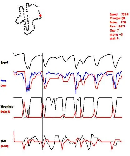
Another thing to mention here is that humans also have "predictive" capabilities that can be learnt. This means that even though the control system has latency, a person can steer etc ahead of time in anticipation of the event occurring, instead of during the event, to compensate for the latency in the control. This is why professional drivers can reduce lap times by out-braking others on the track, in that they can accurately predict where to start braking at the maximum rate before a corner to get to the corner entry speed, despite the vehicle not being able to accurately track the control input because of vehicle physics and inertia. Doing so means that you spend the least amount of time braking, and spend a higher percentage of time on the track at a higher speed, resulting in a higher average speed overall and the shortest lap times. (Sorry but this isn't really a skill they use much in the Indy500 on a loop!) Funnily enough, like on a PC racing simulator using a keyboard, you can be pretty fast around a track with just a digital on/off switch for accelerator and braking, if you train that technique. Have a look at how steep the throttle/brake graph is here, in comparison to speed and acceleration forces that result. They are always going from maximum acceleration to maximum deceleration of available traction.


4501417316_1f68b4b0a8.jpg


If you consider the low latency of GPU processing of near real time game rendering, you can sort of get a feel for just how crazy fast processing and control is nowadays, way beyond human perception. So although there is a measurable latency, for all intents and purposes in the context of human capability, it has a negligible impact of control loop performance given our own high latencies and variablities.

Just to come back to the SBW in the CT, my comment regarding the progressive steering nature, of steering more than the steering input so that you have steering lock within one rotation of the steering wheel, this is actually complementary to human steering behaviour. I found this t be the case on my Landcruiser that had electrically assisted mechanical variable rate steering. Often the center dead-band on steering wheels at higher speed (the area where you can move the steering with little steering output) means you often feel like there is no to little output, so you often jerk the steering wheel to get a response. Over time though, you get used to responsiveness outside of the dead-band, and more often than not you end up with better steering inputs overall, because the steering ratio near the center allows for better fine control, whilst the ends allowing for more cornering with less input, and because that typically happens at lower speeds, means a smoother driving experience overall as you don't have to fumble over the steering wheel at full lock with uncoordinated hand movements.
Sure, I could hack up a control system with response in the single-digit milliseconds using just a Raspberry Pi. This isn't the science of rocketry.

The issue with the Audi IMHO is that they're processing the user inputs through their ADAS computer to override/mitigate those inputs for safety, traction control, etc. The ludicrous +100ms delay is occurring in the compute phase.

Fortunately, Tesla engineers have become experts at minimizing the delay between visual input and control output in their FSD package, so they should probably have no trouble with SBW.

However, given the existing systems (Audi etc.), the latency is a legitimate concern.
Sponsored


RVAC

Well-known member
Joined
Aug 11, 2021
Threads
1
Messages
864
Reaction score
1,291
Location
-
Vehicles
-
That image shows no front and rear casts whatsoever, nor any definition of a structural battery pack, both of which do more than any skin surface on the vehicle.

It's just a placeholder to show the "intent" of the design, and it's form, but in no way indicates if the exterior is structural or not.
Whether the exterior is structural or not has already been discussed ad nauseam. The point I'm making is different, what that render denotes is that there is no evidence Tesla has walked back on their definition of "exoskeleton", however inaccurate that may be. The fact that the cabin structure of the "placeholder" is almost identical to that of the production vehicle is quite telling.


As for changes, we know it's not the same length, not the same angles etc, so yes it has changed.
To the better as far as I can tell. ;)
Referring to the vehicle architecture, changes to length, angles etc... are beside the point. As for the better I'm not quite sure :LOL:
 

JBee

Well-known member
First Name
JB
Joined
Nov 22, 2019
Threads
18
Messages
4,913
Reaction score
6,362
Location
Australia
Vehicles
Cybertruck
Occupation
. Professional Hobbyist
Country flag
You're assuming that all loads apply force at 90º to the ground, equally across all wheels. Lateral and unequal forces will cause the body to twist, which is resisted by exterior panels and glass.
Not at 90 degrees, but rather to the nearest fulcrum or point where the load or force interacts with the ground. In this case it's just the tyre contact patch.

There is no force applied to the vehicle in operation that does not effect the tyre patch, until the body itself collides with an obstacle.

Likewise, you can't apply force to a lever that is not constrained by a fulcrum in the opposing dimension to where the force is applied. So for a force to be applied, there needs to be something to push against, otherwise the force can't be generated in the first place.
 

JBee

Well-known member
First Name
JB
Joined
Nov 22, 2019
Threads
18
Messages
4,913
Reaction score
6,362
Location
Australia
Vehicles
Cybertruck
Occupation
. Professional Hobbyist
Country flag
Sure, I could hack up a control system with response in the single-digit milliseconds using just a Raspberry Pi. This isn't the science of rocketry.

The issue with the Audi IMHO is that they're processing the user inputs through their ADAS computer to override/mitigate those inputs for safety, traction control, etc. The ludicrous +100ms delay is occurring in the compute phase.

Fortunately, Tesla engineers have become experts at minimizing the delay between visual input and control output in their FSD package, so they should probably have no trouble with SBW.

However, given the existing systems (Audi etc.), the latency is a legitimate concern.
I'm unfamiliar with Audi's system, however, I doubt the integration into their ADAS system has any more latency than the ESP/ABS/Traction control loops from any other manufacturer that all operate in the 10ms range, and that has greater steering capacity by differential braking, than the steering angle by itself.

But even if it did have such latency because of ADAS, I don't think that implementing such ADAS based steering conditioning is necessary in order to make a production SBW system, as it would work fine without it, provided at a minimum it emulated a mechanical steering.

I'm struggling to imagine why processing or control should have latency issues these days. I also can't think of a specific vehicle dynamic that occurs so fast it and needs so much processing at the same time, that it would cause latency, even in a simple couple of dollar worth MCU. (Let alone multi core and thread CPU/GPU) You could also run a dedicated FPGA if you needed more bare metal performance. These things operate in the 100's MHz and GHz range respectively.

Maybe it's latency from the actuation side? Also sounds unlikely somehow. Might have to have more of a look at what could be the reason these guys have 100ms latency.

BTW we used to run Ardupilot code on the Raspi, but MCUs are way faster, cheaper and more reliable to run Autopilot code on than a full Linux stack.
 

Crissa

Well-known member
First Name
Crissa
Joined
Jul 8, 2020
Threads
138
Messages
19,571
Reaction score
31,475
Location
Santa Cruz
Vehicles
2014 Zero S, 2013 Mazda 3
Country flag
The gigacastings can't carry all the weight of the vehicle since...

...They don't even connect to one another.

-Crissa


PilotPete

Well-known member
First Name
Pete
Joined
May 8, 2023
Threads
12
Messages
1,578
Reaction score
3,969
Vehicles
Porsche, BMW, M3LR on order
Occupation
Chief Pilot
Country flag
No worries. We might have to go into some detail after all so I can explain it better, step by step.

I would like to at first clarify which "skin" parts in particular are actually attached to the underlying body to be useful structurally, as there are various parts of the vehicle that are structural and other that are not, depending on the load path.

The body (in white) does bear load, but the skin does not, because there is no load on the skin for it to bear.

Imagine a crane that is lifting something, half way along the lifting arm like in this diagram.

Buildings | Free Full-Text | Location Optimization of Tower Cranes on  High-Rise Modular Housing Projects


What added structural advantage does the remainder of the lifting arm provide to the crane, that extends to the right, past the point the load is attached in it's current position?

Likewise, the body in white (BIW) is already structurally sound and self supporting, without any stainless "skins" attached:

Tesla Cybertruck Some very apparent steer-by-wire action! {filename}


The above shows front and rear cast and cabin frame, probably without the structural battery underneath. Now if you add to that every "moving" stainless panel to the frame, being the doors and frunk, and then the top glass windscreen and the rear windscreen, and the structural battery from underneath, you will end up with only the four quarter fenders missing, one on each corner that are actually still made of the stainless steel skin.

The components in that BIW structure will support most of the load by itself without any skin attached however, only the fender quarter panels are stationary, and can actually be rigidly be attached so that they could carry a load together with the BIW. That is "if" there was a load at that point they could carry, as per the crane example.

So lets explore where the loads originate in comparison to the fenders, as to identify what loads, if any, could be supported by the fenders:

The front fender is external of any load, as you can see the front cast has the drive train sub-assembly points, that also supports the suspension. The fender does not offer any meaningful geometry to intercept the load from between the wheel and the frame from the suspension, to the point the suspension is not connected to the fender in any way. Note the sub assembly is attached to the frame on the inside of the suspension arms, with the airspring riser being supported into the top of the front cast recess, that is located directly underneath the a-pillar of the cabin frame and windscreen. (which you can see in the second picture below)

Tesla Cybertruck Some very apparent steer-by-wire action! {filename}


Tesla Cybertruck Some very apparent steer-by-wire action! {filename}


Try to imagine from where a operational load/force can be applied to the front fender, or even harder where a force should originate from on the vehicle in it's normal state, that then needs to find a path to the suspension parts. You could lean on the fender, sit on the fender, maybe place a cement bag on the fender, and the fender would have to resist that force. But is that where you would load the CT? Unlikely.

You could even twist the vehicle for torsion, but those forces are only directly in between the suspension assemblies that is attached internally to the cast, cabin frame and structural battery, and as such would only influence the relative force on each wheel, through those parts, but not something that lays outside of the load path, being the fender. In the front there is little to no load to support in the vicinity of the fender, considering that the HVAC and frunk sit inside the cast frame, so would it be beneficial to have a meaningful rigid connection from the cast to distribute load through the fender? No it's not, and that is why you don't see very much in the way of connection points on the cast to connect the fender. The front fender has a bunch of other roles, (aero, wheel guard etc) but structural support is not one of them. In a failure mode, like for crash impact protection, all the skin panels play a roll as they are compressed against the BIW, so the fender is definitely doing something, so it's worth having, but it is not supporting the vehicle mass structurally.

In the rear it is a little different, in that depending on where the bed is loaded there might be some addition force on the rear fender, or rear sail panel. Originally this was split to house storage behind it, but now it's likely without storage. However, as you can see in the picture below the cast structure is along the internal wall of the bed, not the external wall of the CT. As such it also doesn't have any meaningful interconnection to the skin to transfer forces through the fender. In the rear of the cast you can actually see the mounting points for the tailgate hinge and locks if you compare the two photos below.

Tesla Cybertruck Some very apparent steer-by-wire action! {filename}


Tesla Cybertruck Some very apparent steer-by-wire action! {filename}


The skins, as are the door skins, a quite a distance from the cabin frame and casts. But once again, lets go back to where the load/force originated from, and where it has to go to to get to the wheels.

The bed itself would connected to the cast, and I think it is sitting on top of the flat spot next to the rear wheel arches, along with across the front under the bed front wall (midgate), and spanned across the rear tailgate. Like a pallet. The point here is that directly underneath those flat spots near the wheel arch, are also the suspension springs for the rear axle, where all the load from the bed must go anyway to get to the ground. So the fastest route for load in the bed to be supported by the wheels is through the suspension, the cast and then the bed that sits on the cast. The fender is not in between the load and the suspension, so no load will be transferred out to the fender, and then back into the cast and suspension down to the wheel. (Once again like the crane example above)

Now in torsion, we have the same as with the front fender, in that the force is between the wheels only, until that time that one wheel leaves the ground, or the body of the vehicle touches the ground by over compressing the suspension or being wedged by the ground. Once again the load is inside of the lifting arm, and the fender plays no role until the outside of the vehicle touches the ground which will result in damage of the vehicle like any other vehicle.

In fact this highlights another reason "not" to connect the quarter panels to the casts to structurally transfer load, and that is that the stainless steel skin sheet is fairly two dimensional, in that it barely has any depth in it's geometry, unlike a stressed skin aircraft fuselage that is fully circular, the CT skin is just a flat plane. This means that "if" a load was put on it unevenly, it's likely that it would result in enough twisting of the skin, that you could visibly see it in the reflective surface of the CT.

Either way, I don't see any advantage whatsoever, in trying to get the skin, which is outside of the suspension, to carry any load of the vehicle. Neither do I see any meaningful load being transferable to the suspension via the skin.

I'm curious if you can find one for us to discuss.


Specifically, he has shifted mass from a conventional chassis frame that is common in most trucks, to a unibody/monocoque body design, like the BIW CT shown above. But this is far from new, because every unibody has done this before for decades, and the cabin and front and rear assemblies (now casts with Teslas) have always formed their primary structure.

I don't seek to diminish the result of the CT design in any way, only to highlight that the skin plays no important role in it's structure under operational loads, but rather only as crash protection in a failure mode.

The trick, more than everything here, is that the "combination" of all these changes has resulted in the CT design, and that optimisations like the structural battery, or castings have done far more for rigidity and stiffness, and load carrying capacity than the skin on the fenders.

We could hark on here further, about "if" moving the mass from the chassis to the skin helped structurally, more than some other internal space frame or actual stressed member fuselage, which would by far outperform the CT at a lower total weight. For example the total of the CT SS 3mm skin is nearly twice as much weight as a stripped F150 chassis frame.

That's not even hard to do to, but will it have all the openings, and functions, and repair ability, or ease of manufacturing and assembly for all the other components that are needed for a fully functional vehicle. No it wouldn't. Like every design, it's just going to be the best possible compromise to accommodate all the design priorities of that product, for this iteration of it.

And on that note, I haven't been this "excited" by car developments, since the advent of hybrids decades ago. Now what EM wants to call it, or what he thought is was, or what we thought it was, well that's not the same thing as what it actually is at this time, so I'm fine in saying it is exactly what EM wanted, but on reveal what he wanted, wasn't what we thought he said! :p
Tesla Cybertruck Some very apparent steer-by-wire action! IMG_2025


Here is where your example falls short. You are considering only the vertical load and the crane is balanced. If you are trying to maintain the 90 degree angle (in red) and the crane is NOT balanced, then you could attach a plate (in green) to the vertical and horizontal beams, increasing strength against that deformation. However, if you attach the beams to the blue plate (out where your vertical stress isn’t carried) then you have a greater resistance against deforming the perfect red 90 degree angle. So behind the cab where the two arms stick out, the skin MAY assist in structural rigidity in attaching those pieces and allowing them to operate as One, sharing any load.

The bed of the CT may sit on that casting, but it hangs out well past it. And the triangular sides provide for a supported tail and increasing the load the bed could carry.

As to the torsional rigidity, should the RF tire hit a bump, the vertical acceleration at that point, transmitted by the suspension to the body (even if it bottomed out) and the body will want to flex in the middle, both F/R and L/R, creating a twisting moment. The CT should be stiffer than a ladder frame in that aspect.

For the front fenders, I have no idea what they reinforce, outside of an accident. You got me there.
 

Scott Beall

Well-known member
First Name
Scott
Joined
Dec 5, 2022
Threads
4
Messages
83
Reaction score
149
Location
USA
Vehicles
2017 Grand Cherokee (dd), 1966 Mustang, 1967 Corv
Country flag
If it's steer by wire, presumptuously you could change the location of the steering wheel, right? Like, it doesn't have to be in front of the driver's seat? For instance it could be on a control panel like an RC car?
And maybe make it simpler to build trucks with steering wheel on the right side of the cabin for "drive on the right side of the road" friends...
 

JBee

Well-known member
First Name
JB
Joined
Nov 22, 2019
Threads
18
Messages
4,913
Reaction score
6,362
Location
Australia
Vehicles
Cybertruck
Occupation
. Professional Hobbyist
Country flag
Tesla Cybertruck Some very apparent steer-by-wire action! {filename}


Here is where your example falls short. You are considering only the vertical load and the crane is balanced. If you are trying to maintain the 90 degree angle (in red) and the crane is NOT balanced, then you could attach a plate (in green) to the vertical and horizontal beams, increasing strength against that deformation. However, if you attach the beams to the blue plate (out where your vertical stress isn’t carried) then you have a greater resistance against deforming the perfect red 90 degree angle. So behind the cab where the two arms stick out, the skin MAY assist in structural rigidity in attaching those pieces and allowing them to operate as One, sharing any load.

The bed of the CT may sit on that casting, but it hangs out well past it. And the triangular sides provide for a supported tail and increasing the load the bed could carry.

As to the torsional rigidity, should the RF tire hit a bump, the vertical acceleration at that point, transmitted by the suspension to the body (even if it bottomed out) and the body will want to flex in the middle, both F/R and L/R, creating a twisting moment. The CT should be stiffer than a ladder frame in that aspect.

For the front fenders, I have no idea what they reinforce, outside of an accident. You got me there.
I suppose this is the problem with using a 2D drawing as an analogy to explain the "where is the load originating from" problem.

So although your description and changes to the diagram might make sense on the surface, they ignore the point being made with it, and that is the actual position of the load in the diagram. My opening statement was, that for a load to be carried by the fenders, there must also be a load applied to them. No load = no carrying.

Adding the blue rectangle plate doesn't mean there is a load on the area to the right of the green plate, nor does it alter the location of where the load is in the diagram. The load is still transferred by the green plate, and the load ends at that point where the green plate ends. It doesn't go from the load out to the end of the arm and then down the blue plate, rather it goes straight down to the tower on a diagonal line from the point of the load. In fact you could chop the rest of the green and blue plate off on a diagonal and it would still work. Just like if you took the fender off, the BIW would still carry the load, as is the case in the BIW photo.

Further, in that diagram you are mis-representing the location of the actual fender in the diagram, in reality it is only to the right of the load, and not to the left of the load whatsoever. The fender is in no way inbetween the load and the suspension spring (tower). Sorry, I think that by abstracting the load path that way, it led to you to superimposing the CT rear structure onto the simple line diagram and it is complicating the visualisation of the problem.

In reality, if looking from the rear, the CT line diagram is more like a gantry crane like the below, with the two towers, being the suspension spring towers of the rear axle, and the fenders being mounted outside of the towers as depicted by the grey triangles. Remember, like the front, the load in the bed is between the towers, not on the outside of it, so unless you put something on the fenders in this diagram, there would be no load transferred to the towers from them.

Tesla Cybertruck Some very apparent steer-by-wire action! Motions-of-the-3D-gantry-crane-and-payload


Now there is a possibility to use the fenders for stiffening torsional loads in the bed area, by allowing it to take load when the cast deforms. But the bending modulus of different materials also plays a roll, in that unless you carefully calibrated the aluminium cast to match the deforming characteristics of the stainless steel fender, you would experience material fatigue through load cycles, resulting in fractures of the cast or the stainless. Depending on which moved more in relation to the other under load. The easiest way to deal with this is to ignore routing loads into the fender by mounting it on rubber bushes.

Let alone trying to match up the different material thermal expansion rates which would create forces beyond those of the loads being put into the bed. (Alu is 21-24, whilst SS is exactly 17.3)
This is why they have soft bushes between different parts of the car, as the exterior heats and cools differently from the interior, and those result in length changes that need to compensated for in a soft material.

This is similar to a bitmetal thermostat, where each layer of material would expand differently. (btw this is also why you can't use aluminium as bar rein-enforcement for concrete, and only steel, because steel and concrete have the same thermal expansion co-efficient)


Lastly, if we look at the rear fenders pictures, it's fairly clear from the mounting brackets that they are not intended to carry bed load. You can see the black right angle plates with holes for fasteners are not in the direction of the torsional loads, and would simply bend that mounting bracket. For it to do something it would have to be attached to the rear wall of the cabin so that it can adsorb tension and compression forces across the top diagonal of the panel. Like the diagonals of the cast structure. Those little tabs won't cut it, and are instead just there to attach and adjust the panel to the BIW frame.

BTW if there were any more meaningful attachment points under the panel, then they would only be able to reach and attach to the cast, but not the cabin frame, meaning once again, the cast is supporting the panel, and not the panel the cast for any load. So there is no meaningful "exoskeleton stainless steel skin" for operational loads and this idea should be laid to rest.

Tesla Cybertruck Some very apparent steer-by-wire action! fender quarter panels
 

CyberFitch

Active member
First Name
Ned
Joined
Jul 18, 2023
Threads
3
Messages
30
Reaction score
24
Location
Atlanta GA
Vehicles
2017 model 70D & 2018 F-150 LTD
Occupation
Student housing
Country flag
That sound is related to the flux capacitor
 

cvalue13

Well-known member
Joined
Aug 17, 2022
Threads
74
Messages
7,153
Reaction score
13,769
Location
Austin, TX
Vehicles
F150L
Occupation
Fun-employed
Country flag
BTW if there were any more meaningful attachment points under the panel, then they would only be able to reach and attach to the cast, but not the cabin frame,
I’m not sure about that last bit?

Pretty sure rear QPs overlap the cabin frame

As for the attachment tabs seen: don’t you think they’re filling all the void between SS and casting with an adhesive foam or something?

At least, they’ve got to be somehow separating the SS panel from reacting with the Al casting
 

Dazureus

Well-known member
Joined
Sep 1, 2023
Threads
7
Messages
264
Reaction score
589
Location
US
Vehicles
'21 Model Y, '24 Cyberbeast
Occupation
Software Engineer - Steering Systems
Country flag
I'm a little late to this discussion party, but I hope I can add some useful information. My background is as a software engineer in the automotive industry with 8 years working on software for instrument panel cluster (IPC) and 4 years on electric power steering (EPS) products. The company I work for makes steering products for the big 3 and other companies that may or may not now include Tesla. I have not worked on any Tesla products during my career, but I've heard some conversations about how they implement their legacy EPS products and have looked at their SbW patent documents out of curiosity. There are way smarter and more knowledgeable people at my company, but I can speak at a high level about the way the hardware and software works in steering systems (at least how it's implemented at my company).

On the topic of redundancy, I have experience with steering products using 2 ECUs, each operating the half of the steering power pack (assist motor w/ control board) phases. The ECUs are on the same CAN bus and communicate with each other internally. Electronic redundancy happens by ECUs talking to each other, verifying critical signals and physical expectations within the steering system. Should calculated values (hand wheel position, motor torque, ect) mismatch, error codes can be logged and output can be adjusted. Should an ECU fail, at least half the powerpack is still operational and the vehicle steering can be partially assisted (drive will feel this) and steering state can be put in a limp-home state. Physical redundancy, should the power steering system fail, is with a traditional mechanical linkage via the steering column.
From the Tesla patent, a phyiscal steering redundancy isn't present, but they implement electric redundancies by doubling everything up. A two handwheel angle sensors, each with their own public and private CAN, each communicate with one of the two power packs. The power packs communicate with each other via an arbitration private CAN. In short, two completely independent EPS that arbitrate steering values via private CAN. This differs from their legacy EPS implementation, which used 2 ECUs, but in a primary and redundant secondary ECU should the primary fail. It looks like in both the Lexus and Tesla implementation, there are no physical redundancies.

As far as latency, I can say that I'm experienced in Autosar implementations, which runs as a real time operating sytem (RTOS). As far as I'm aware, Tesla does not use Autosar, but uses some other kind of RTOS with their own libraries and software architecture. In the software implementations I've worked on, tasks are organized and prioritized with a task scheduler. For steering, the slowest tasks run at 100ms and the fastest at 1ms. Main CAN communications are Rx/Tx at 10ms. In general, some examples of 100ms tasks are things like current/voltage checks and thermal protections. 10ms tasks would be something like inter-ECU communication arbitration, diagnostics handling, and main CAN functions. 2ms tasks would be where most of the assist torque calculations and stability comphensation would take place; stuff the driver would feel. I've only seen one implementation for 1ms tasks, and it's for Private CAN stuff between two different ECUs that need safety critical information processed. I'm not sure how there could be 100ms of latency between handwheel angle input and wheel input, but I'm guessing it wasn't because of the software implementation.

The videos shown in this thread make a compelling argument for the Tesla implementation of SbW in the Cybertruck, but just because the rear steering is SbW, doesn't necessitate the implementation in the front steering. Images of the Cybertruck front casting indicates a pass through for a steering system, but the Tesla SbW patent doesn't detail the length of the steering column, so it's difficult to say if the firewall passthrough is for a traditional steering column or if the SbW steering gearbox is installed forward of the firewall.

I'd be happy to field any steering questions to the best of my limited ability. I haven't personally worked on SbW systems, but the software implementation at my level fairly close and I have seen the hardware around the office. I can say with nearly 100% confidence that the SbW components I've seen in person are not for Tesla and the projects I've worked on were for the big 3.
Sponsored


Top