Sponsored
EWELON
Well-known member
- First Name
- Rori
- Joined
- May 21, 2025
- Threads
- 28
- Messages
- 560
- Reaction score
- 619
- Location
- Wynnewood,PA
- Vehicles
- 2021 Model 3, 2025 Cybertruck AWD
this is one of the most active topics in the forum right now. find one of the bigger threads and post your info there for people to see. your VIN would be the most useful along with your charging habits.
CyberGus
Well-known member
- First Name
- Gus
- Joined
- May 22, 2021
- Threads
- 91
- Messages
- 10,236
- Reaction score
- 33,889
- Location
- Austin, TX
- Vehicles
- 1981 DeLorean, 2024 Cybertruck
- Occupation
- IT Specialist
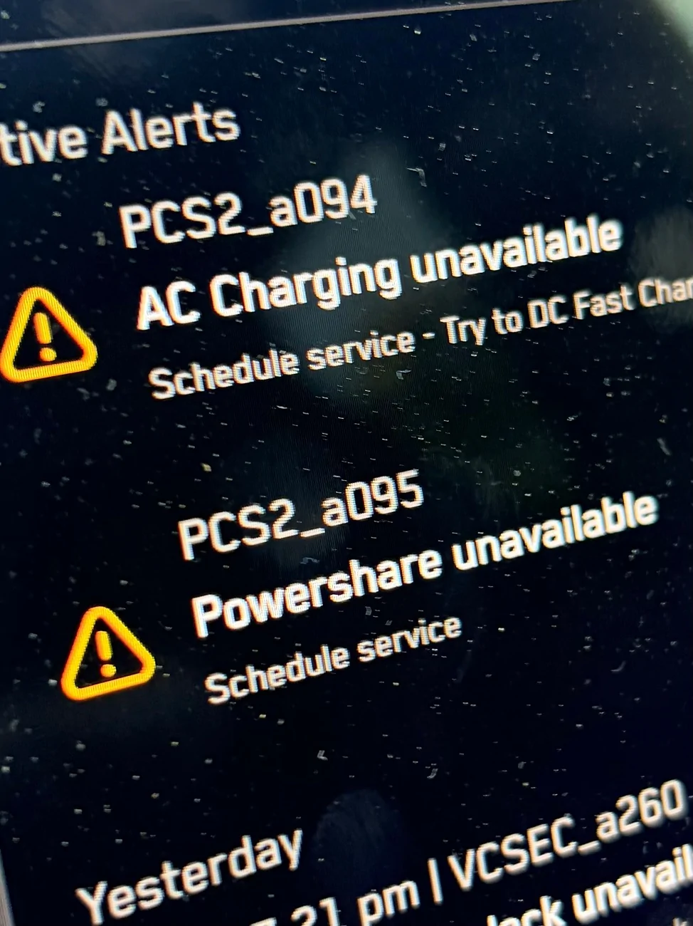
Truck wouldn't charge beyond 24A

EWELON
Well-known member
- First Name
- Rori
- Joined
- May 21, 2025
- Threads
- 28
- Messages
- 560
- Reaction score
- 619
- Location
- Wynnewood,PA
- Vehicles
- 2021 Model 3, 2025 Cybertruck AWD
I would def buy this sticker
mongo
Well-known member
- Joined
- May 27, 2024
- Threads
- 5
- Messages
- 4,520
- Reaction score
- 5,497
- Location
- SE Michigan
- Vehicles
- Cyberbeast
Which culminates inI feel like at this point we need a "my OG PCS survived" sticker.
"Turn in your OG PCS card"

Mini2nut
Well-known member
- Joined
- Apr 2, 2020
- Threads
- 138
- Messages
- 4,069
- Reaction score
- 7,380
- Location
- Planet Earth
- Vehicles
- *Tesla MYP *SAWD Cybertruck ordered 2/20/26
The big question: Have Tesla engineers discovered the root cause of failure and updated this $1700 part?
Eka
Well-known member
- First Name
- Ekaterine
- Joined
- Feb 20, 2026
- Threads
- 1
- Messages
- 210
- Reaction score
- 200
- Location
- The land between two rivers.
- Vehicles
- Model Y, Cybertruck
- Occupation
- disabled
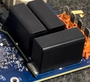
I think it is a soldering issue. The power FETs are pick-n-placed and soldered on the bottom of the PCB first, then the top side parts are pick-n-placed and soldered. During that top side soldering, the bottom side FETs' solder melts and they no longer sit flat. The FET's documents even said they needed to be soldered last.The big question: Have Tesla engineers discovered the root cause of failure and updated this $1700 part?
mongo
Well-known member
- Joined
- May 27, 2024
- Threads
- 5
- Messages
- 4,520
- Reaction score
- 5,497
- Location
- SE Michigan
- Vehicles
- Cyberbeast
Or the "top" went through first with the large parts glued down and the FET side was done last.I think it is a soldering issue. The power FETs are pick-n-placed and soldered on the bottom of the PCB first, then the top side parts are pick-n-placed and soldered. During that top side soldering, the bottom side FETs' solder melts and they no longer sit flat. The FET's documents even said they needed to be soldered last.
Seems like if they did ignore TN1378, there would be more obvious effects than just a little vertical sag/ misalignment.
Eka
Well-known member
- First Name
- Ekaterine
- Joined
- Feb 20, 2026
- Threads
- 1
- Messages
- 210
- Reaction score
- 200
- Location
- The land between two rivers.
- Vehicles
- Model Y, Cybertruck
- Occupation
- disabled
The remelting of the solder and hanging there suspended by the solder helps improve centering of the part.Or the "top" went through first with the large parts glued down and the FET side was done last.


Seems like if they did ignore TN1378, there would be more obvious effects than just a little vertical sag/ misalignment.
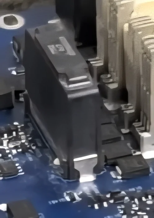
I'd need to see a current board to know what they are now doing. The board Monro had definitely had FETs that were not parallel with the PCB. The impressions they made in the heat transfer goop looked like the FETs were off angle like the bottom side FETs for a board I designed. When we moved all the FETs to one side and soldered it last, it fixed the thermal problem. Thin supports during soldering can also be used to keep the parts level.
wb9vxy
Member
- Joined
- Jun 9, 2024
- Threads
- 5
- Messages
- 20
- Reaction score
- 18
- Location
- Los Osos CA
- Vehicles
- 2022 Y, 2024 X, 2024 CT
Truck wouldn't charge beyond 24A, after a few days got a 2 active alerts. Took it in for service today and they said it's a known issue happening to a lot of trucks, so much so they have put out a bulletin.

wb9vxy
Member
- Joined
- Jun 9, 2024
- Threads
- 5
- Messages
- 20
- Reaction score
- 18
- Location
- Los Osos CA
- Vehicles
- 2022 Y, 2024 X, 2024 CT
I just went down to 24A charging on my CT.
I have a couple of road trips coming up.
Does the AC failure portend 48V converter failures and a bricked truck or or folks
seeing that the 48V portion of the PCS2 continues to home along?
Tnx
T3
I have a couple of road trips coming up.
Does the AC failure portend 48V converter failures and a bricked truck or or folks
seeing that the 48V portion of the PCS2 continues to home along?
Tnx
T3
mongo
Well-known member
- Joined
- May 27, 2024
- Threads
- 5
- Messages
- 4,520
- Reaction score
- 5,497
- Location
- SE Michigan
- Vehicles
- Cyberbeast
Charging (DCAC) failures seem to be independent from 48V (DCDC) failures.I just went down to 24A charging on my CT.
I have a couple of road trips coming up.
Does the AC failure portend 48V converter failures and a bricked truck or or folks
seeing that the 48V portion of the PCS2 continues to home along?
Tnx
T3
mongo
Well-known member
- Joined
- May 27, 2024
- Threads
- 5
- Messages
- 4,520
- Reaction score
- 5,497
- Location
- SE Michigan
- Vehicles
- Cyberbeast
What looks like height variation may have been where the pink detached from the insulator rather than the fets. Per a contact, it takes some effort to de-pink the PCB after separation.The remelting of the solder and hanging there suspended by the solder helps improve centering of the part.
I'd need to see a current board to know what they are now doing. The board Monro had definitely had FETs that were not parallel with the PCB. The impressions they made in the heat transfer goop looked like the FETs were off angle like the bottom side FETs for a board I designed. When we moved all the FETs to one side and soldered it last, it fixed the thermal problem. Thin supports during soldering can also be used to keep the parts level.
Sponsored