OP
OP
cvalue13
Well-known member
- Joined
- Aug 17, 2022
- Threads
- 74
- Messages
- 7,153
- Reaction score
- 13,769
- Location
- Austin, TX
- Vehicles
- F150L
- Occupation
- Fun-employed
- Thread starter
- #16
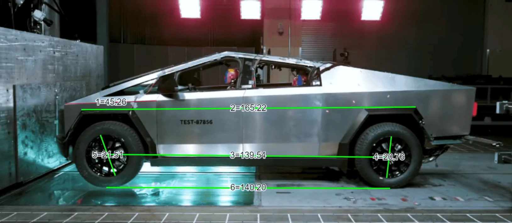
Describe your issue.It's not "in-plane" though. Close, but the estimate will be a bit off.
Take Photo A for example. Maximum the near the plane of the wheel rim is within an 1” or 2” from the where the fender flare is measured junction with the quarterpanel:
Meanwhile, the distortions of depth on perspective are relative by the distance the camera is from the objects being captured. The further the camera from the subject (relative to the distance between two objects in the photo being compared, the less discernible any distortion of depth).
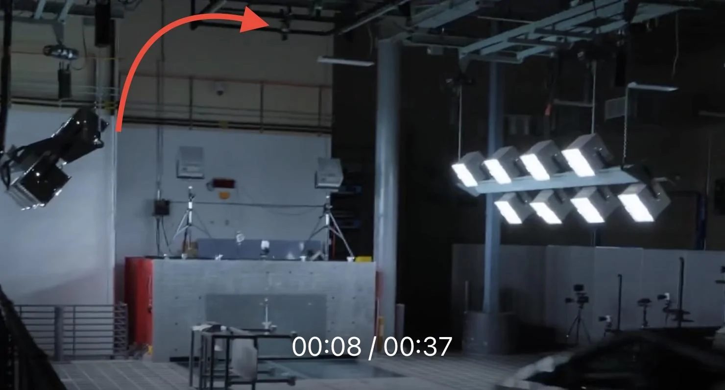
The camera rigs for these tests are place well out out of way of debris - at least 20’ back
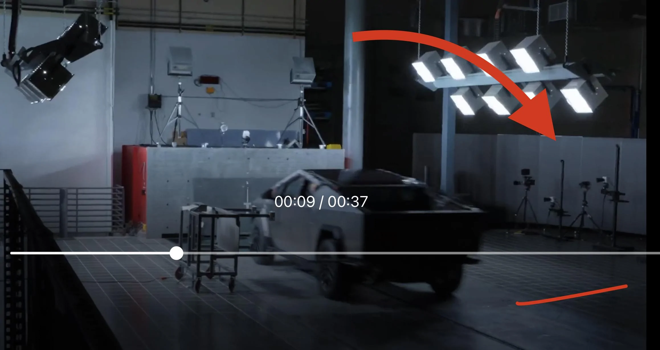
At 20” distance from lens, the ~2”-ish inch delta of depth between rim lip and and quarterpanel’s junction with flare is… nearly zero (pixel resolution is likely a greater hindrance than DOF)
Notice the camera rigs above and to the driver side are all also of at least equal distance from the vehicle. .
These cameras set-ups are designed to allow accurate measurements from distances - it’s basically the point of taking the videos.
But read on …
Respectfully, your drawing only tells me that you’re misunderstanding the measurements, cameras, and camera distances at play here - and the cumulative low levels of distortions at play as a result.Your measurements work fine on a flat surface, but as soon as you are looking at 3d objects with different layers, they get off-kilter rather quickly. Particularly with the Cybertruck’s weird angles.
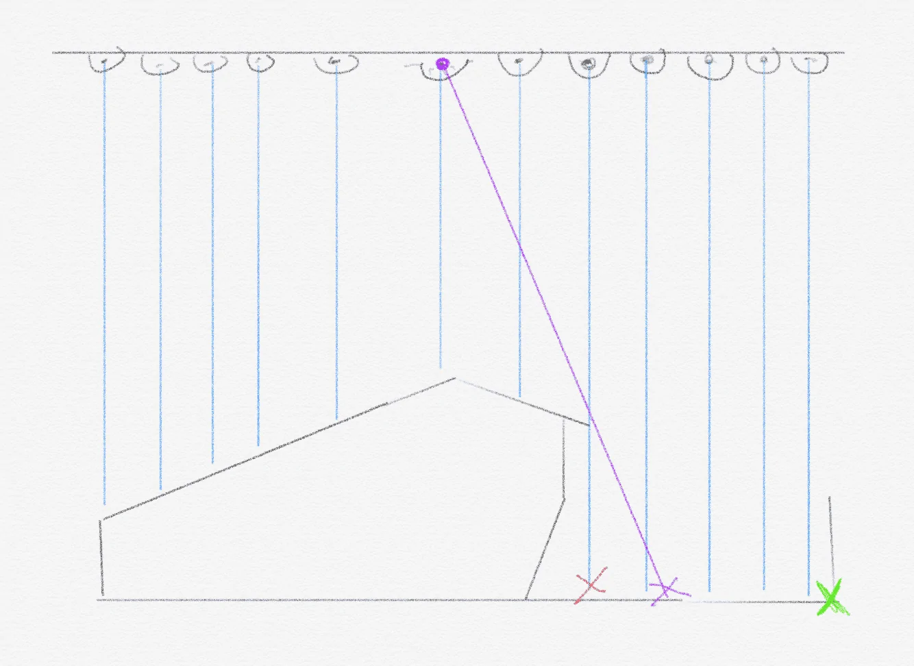
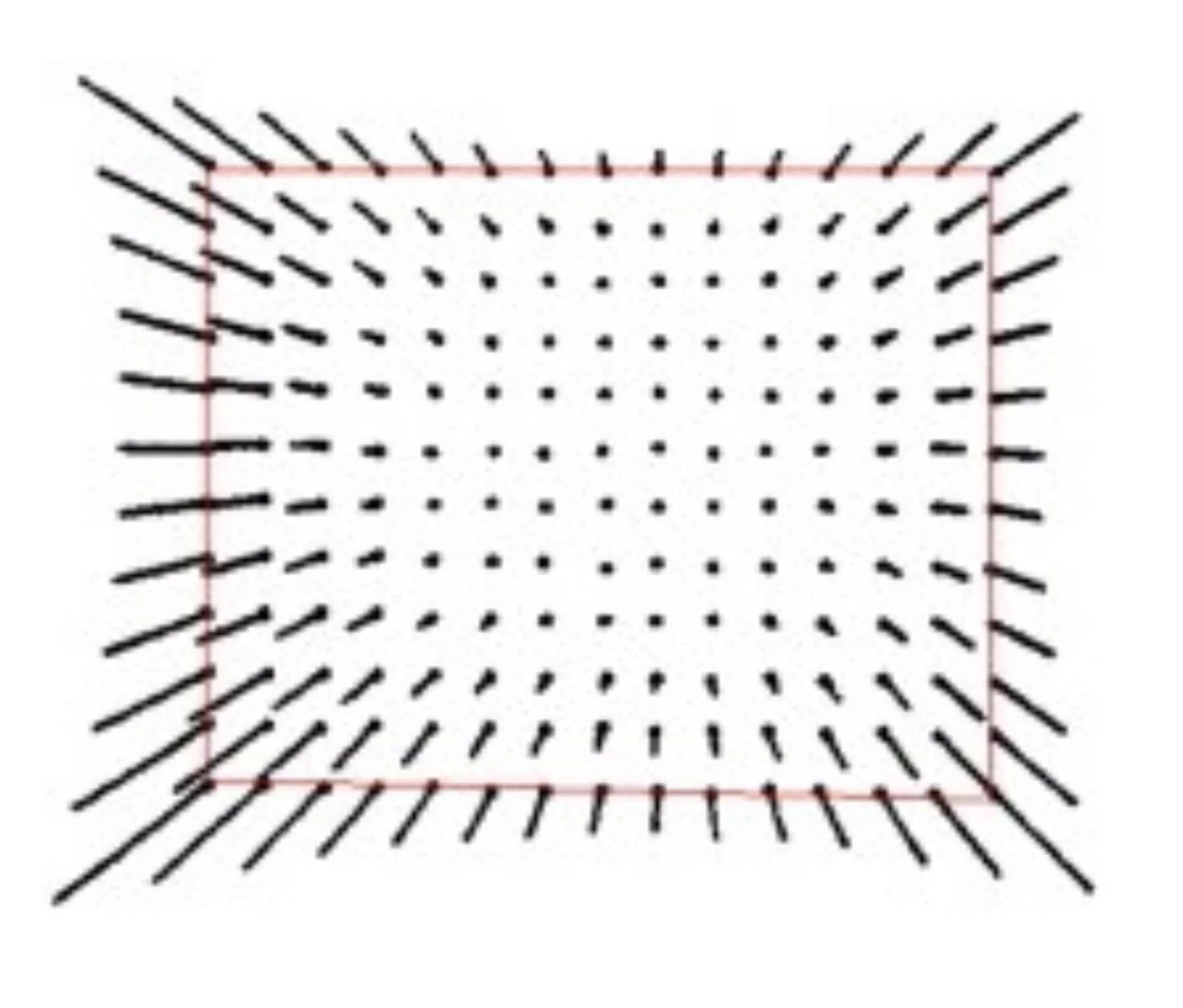
These cameras are not Walmart point-and-shoots. They use large lenses, that greatly minimize radial distortion of the sort you seem to be referencing in your drawing. In effect the lens choice first minimizes radial distortion into this relatively minimal field of distortion:
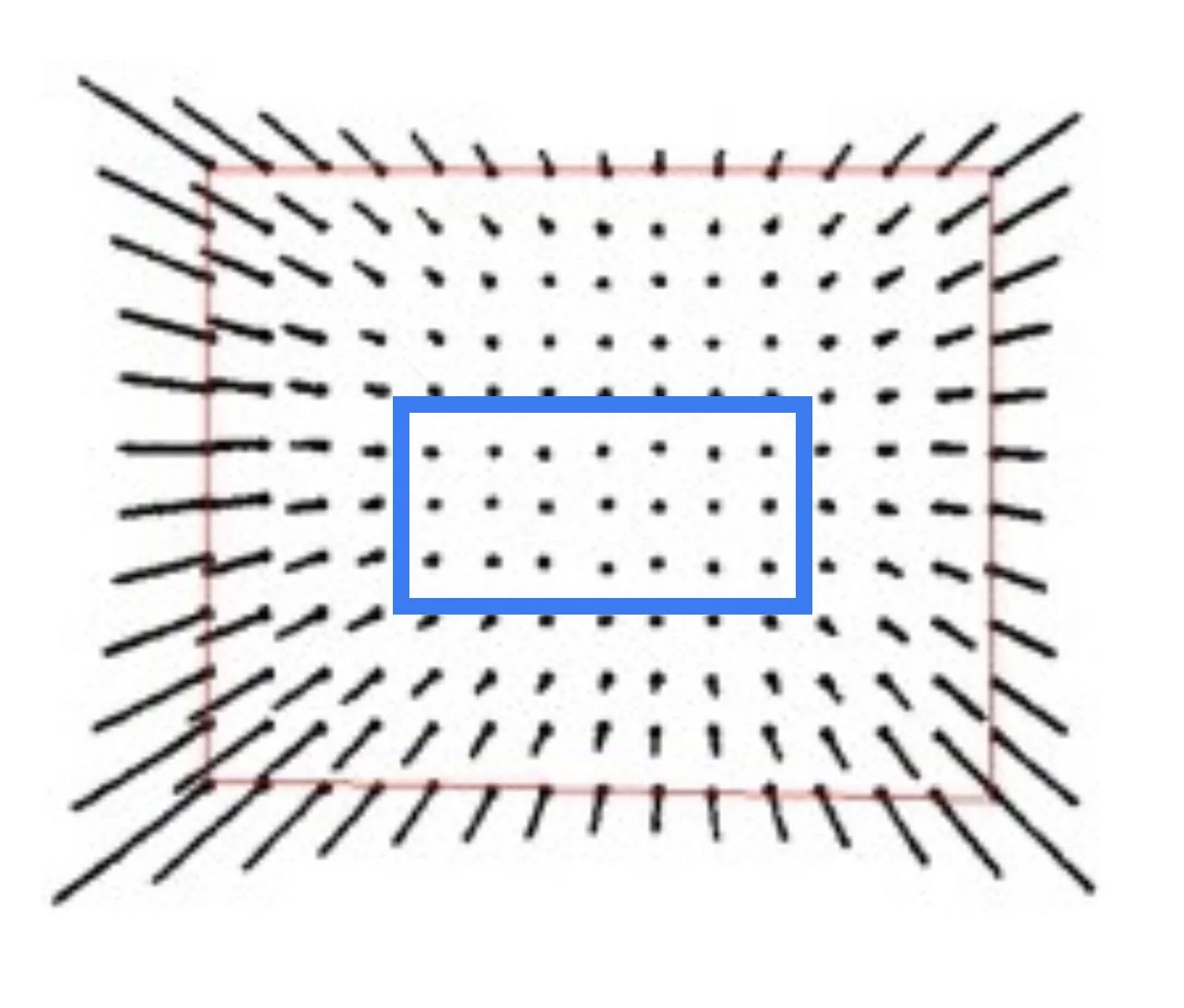
The cameras are then placed at prescribed distance from object coordinates, with prescribed focal lengths, to standardize data collection and further minimize radial distortion. In effect, in the world view diagram above, they place the vehicle like this:
[ As an aside, the video is then subjected to various forms of geometric camera calibration, also known as camera resectioning. These calibrations are used to correct for remaining lens distortion, and measure the size of an object in world units. These tasks are used in applications such as machine vision to detect and measure objects at distance. Put differently, without this type of lens calibration technology, FSD couldn’t work.
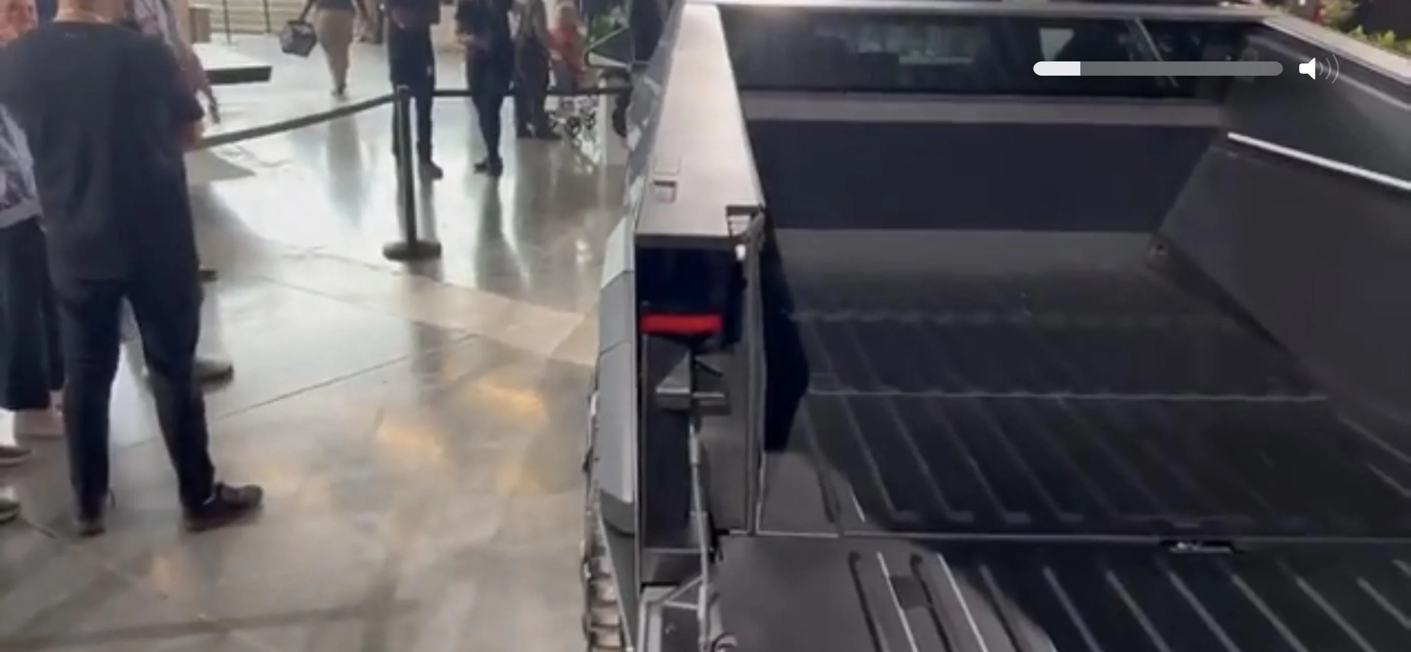
After lens calibration, the relevant portion of the frame to be studie appears like this:

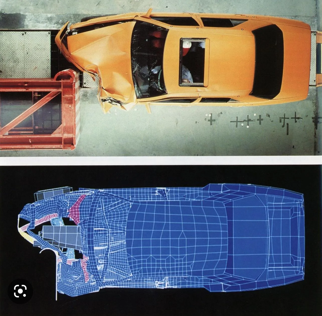
The checkerboard tape typically seen in Tesla tear videos is used for this final data processing, allowing them to ultimately do things like turn the video into accurate 3D models that can account for remaining distortions of perspective in frame, or if vehicle lifts or rotated out of the ideal depth of field. Results like this:
The data processing is a final layer we don’t have access to. But prior to that, the lens choice, distance from camera, focal length, and vehicle envelope placement within frame collectively act to minimize the sorts of radial distortions your drawing seemed to be driving at. So minimized, that the the greater source of any error is likely measurement point selection.
In all, the point of this whole thread was that the Easter Egg within the Tesla crash test video was great ability to make on-screen measurements with even crude tools.
Which is all a medium-depth way of saying:
such facilities generally use cameras placed in locations (and using lenses) that minimize the distorting effects
Sponsored
Last edited: