JBee
Well-known member
- First Name
- JB
- Joined
- Nov 22, 2019
- Threads
- 18
- Messages
- 4,913
- Reaction score
- 6,362
- Location
- Australia
- Vehicles
- Cybertruck
- Occupation
- . Professional Hobbyist
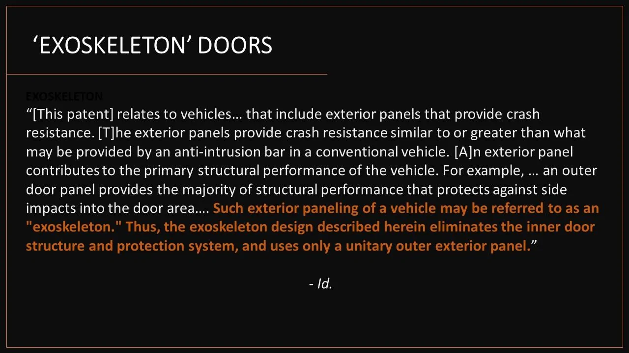
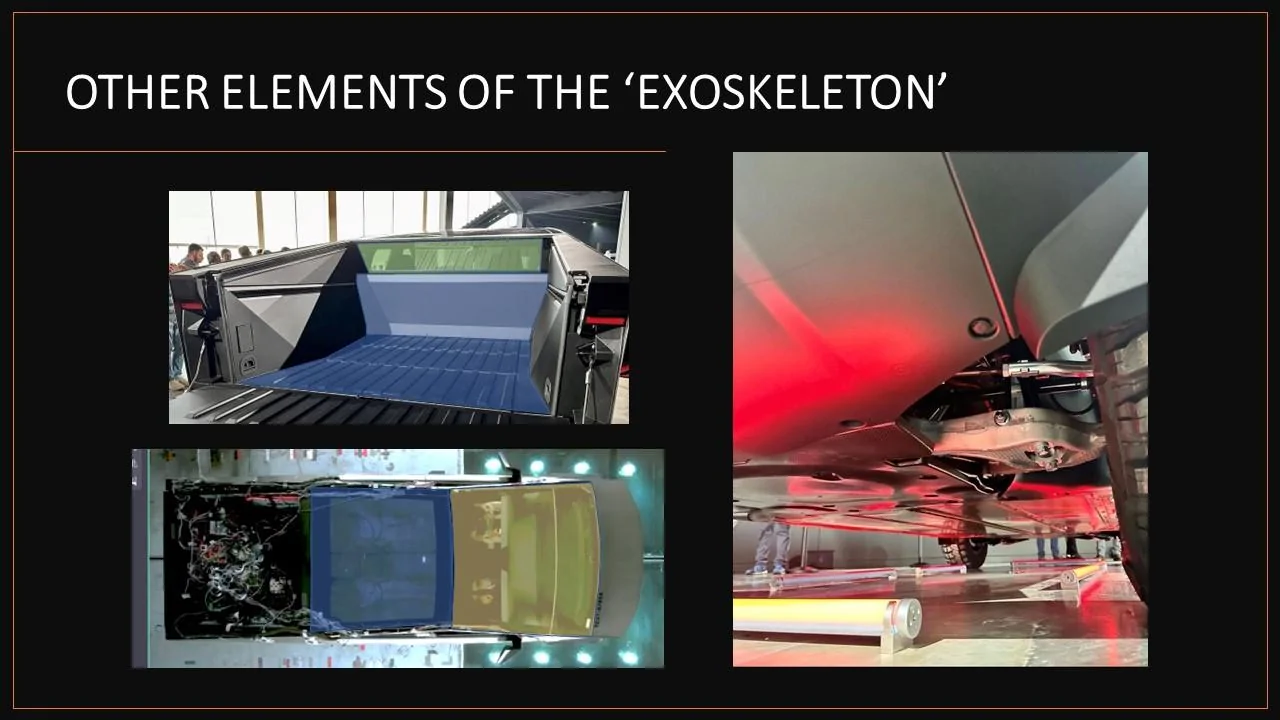
Indeed it is quite bizarre, downright crazy even.I’ll just skip to phrasing it as an assertion:
with half your breath you’re saying the obvious: these forces are borne by bolts and adhesives at joints
with the rest of your breath you’re saying that those same forces cannot be borne by a welded metal bracket across that same joint.
it’s bizzare
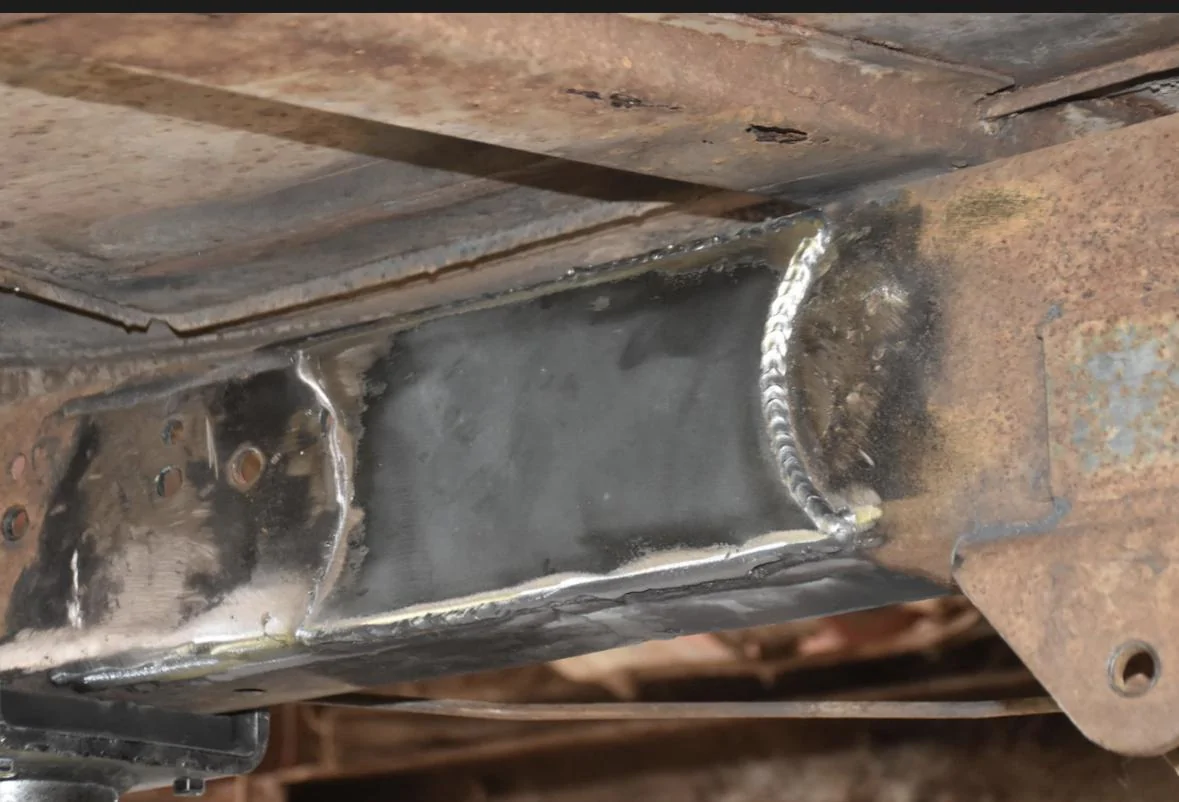
metal mending brackets are used to repair or increase strength of 4X4 frames all the time

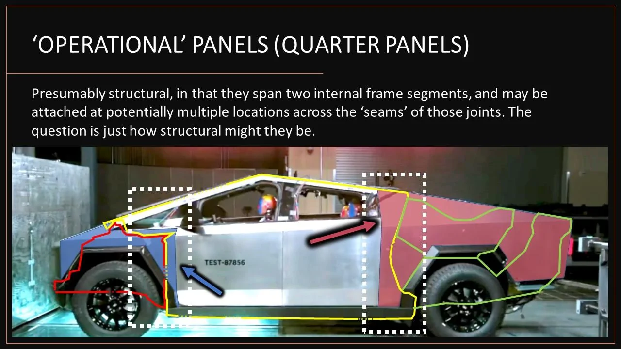
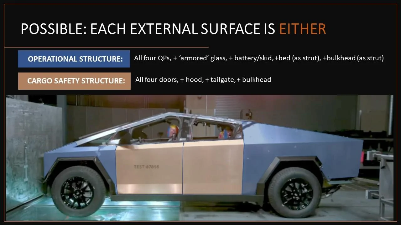
But that is the single line drawing of the load path you want me to believe in, so you can use the fenders structurally.
"IF" you want the fenders to do some structural work, then like the lever arm on the right, you have to get the fender inbetween the load and the fulcrum, so it can help that lever arm.
This is what I mean when I say there is "no load path" through the fenders, because they are "outside" of the load path.
Look again at the diagram below, but ignore all the bias and counterarguments, that you want to find to make your OP points, just consider this line drawing as if it were the only thing we are discussing. Just for one minute at least.
Now imagine that how it is attached together, even what it is made of is all irrelevant, because each part of the single line drawing has infinite strength.
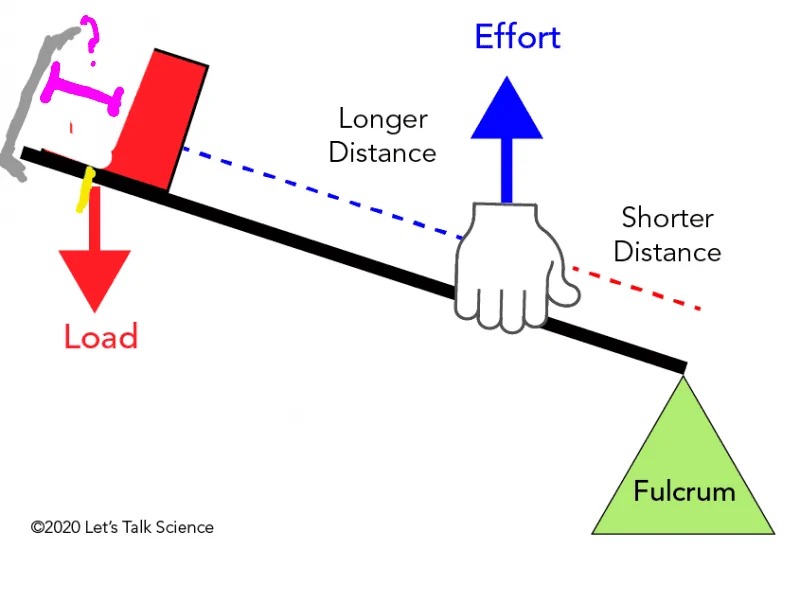
So once again that grey line is the fender, sitting to the left of the load. The load in this diagram can only act on the right hand side of the load, along the blue and red load path line tothe fulcrum. But cannot carry anything to the left of the load, along the pink line, because th we re is no fulcrum to carry it to. It's in the air, flapping in the breeze so to speak.
In this single line diagram the beam right of the load does all the work, the beam left of the load does nothing, except carry the fender in grey.
If we wanted the fender to share some load, the left side of the beam would also need to terminate on a fulcrum, or fixed point as well. If we put the fulcrum there the load would use the left beam and the fender as well, which would reduce the amount of load to the fight fulcrum.
This of course would be beneficial, but It is not haw the fender is attached to the structure on the CT. In the front axle the load sits inbetween both wheels, with each wheel representing a fulcrum to the ground, the suspension arms the levers to the center of the vehicle with the hand being the springs.
But the fender is on the outside of the wheel, like in the drawing, but not even connected to the lever arm bearing the load, nor the spring. Hence my comment that it might as well be in a trailer behind another car. This is not a flipant comment, it is how it is, and why I am so persistent on the point.
Anyway when I get home I'll draw out a sketch how I see the load paths on the CT so we can discuss it better with visual aids so we end up talking about the same thing.
Sponsored